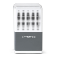
D - 14 Istruzioni per l'uso – Deumidificatore TTK 25 E IT
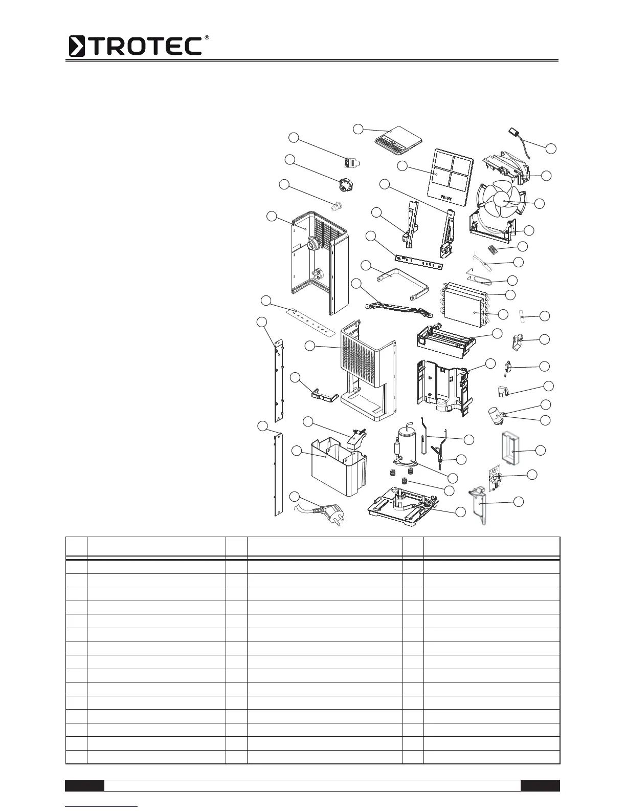
Prospetto dei componenti ed elenco dei componenti
N. Componente N. Componente N. Componente
1 Base pan 16 Sensor (for humidity) 31 Strike
2 Rubber 17 Fixture 32 Handle
3 Compressor assembly 18 Control board 33 PC board
4 Discharge pipe 19 Cover 34 Rail
5 Suction pipe 20 Capacitor (8 μF/450 for compressor (3)) 35 Rail
6 Plate 21 Fix metal 36 Air filter
7 Drainage Pan 22 Cover 37 Top cover
8 Evaporator assembly 23 Micro switch 38 Decorating plate
9 Condenser assembly 24 Fixture 39 Decorating plate
10 Capillary tube 25 Bar 40 Control panel
11 Sensor (for evap) 26 Power supply cord complete 41 Rear panel
12 Fix metal 27 Drain bucket 42 Soft cap
13 Fan tank 28 Float 43 Plug
14 Brushless DC fan 29 Handle 44 Fixture
15 Fan tank 30 Front panel
1
2
3
4
5
6
7
8
10
11
12
13
14
Avvertenza!
I numeri di posizione dei componenti si differenzia
dai numeri di posizione degli elementi costruttivi
utilizzati nelle istruzioni d'uso.