EN 16
Operating manual – dehumidifier TTK 54 E / TTK 66 E
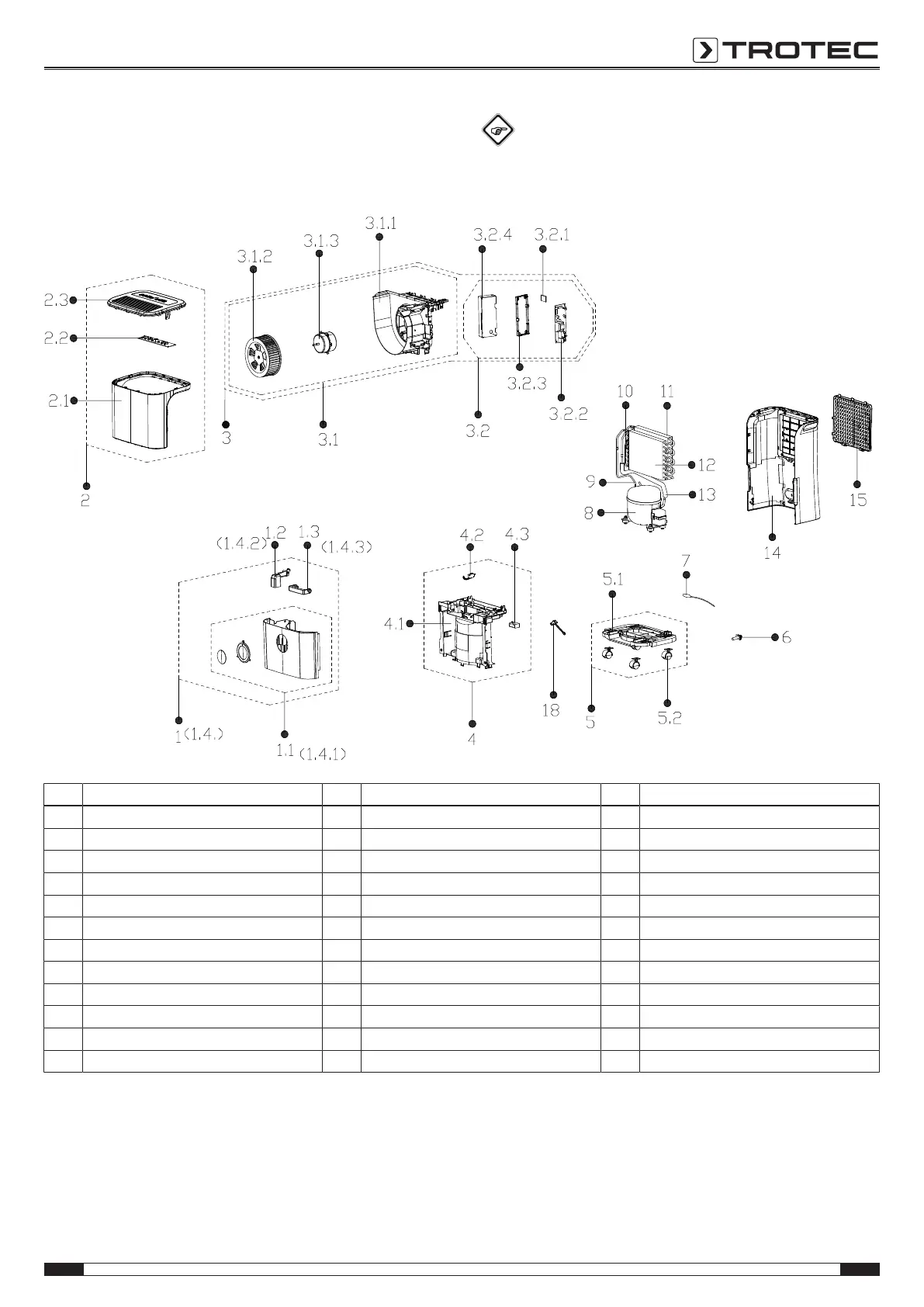
Spare parts drawing and list
TTK54E
Info
The position numbers of the spare parts differ from
those describing the positions of other parts mentioned
in this operating manual.
No. Spare part No. Spare part No. Spare part
1 Water Tank Assembly 3.2 6 Power Supply Cable Subassembly
1.1 Water Tank Subassembly 3.2.1 Humidity Sensor Board Subassembly 7 Temperature Sensor
1.2 Floater tank buoy 3.2.2 Main control board assembly 8 Fixed speed reciprocating compressor
1.3 Handle for Tank 3.2.3 9 Parts of compressor return pipe
2 Front panel assembly 3.2.4 Electrical Control Box 10 Capillary Assembly
2.1 Front Panel 4 Parts of middle clapboard 11 Condenser Assembly
2.2 Display board assembly 4.1 Parts of middle clapboard 12 Evaporator assembly Gas valve assembly
3 Volute shell assembly 4.2 Micro Switch 13 Compressor exhaust pipe
3.1 Volute shell subassembly 4.3 Capacitor 14 Rear Panel assembly
3.1.1 Volute shell subassembly 5 Chassis Assembly 15 Air inlet grille
3.1.2 Centrifugal Fan 5.1 Chassis Subassembly 18 Drain Stopper
3.1.3 Single phase asynchronous motor 5.2 Universal wheel Ionizer