3 Structure and functional description
3.1
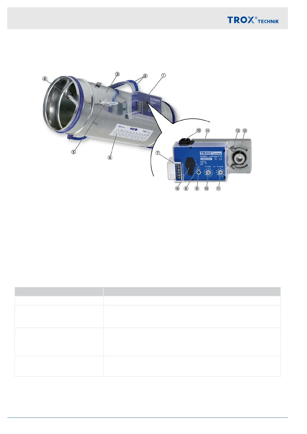
Product overview types LVC, TVR, TVJ, TVT, TZ-Silenzio, TA-Silenzio, TVZ, TVA
Fig. 1: Easy controller mounted on the control unit e.g. TVR
1 Easy controller
2 Measuring hoses
3 VAV terminal unit
4 Sensor tubes of the control unit
5 Wire clamping bracket
6 Scale sticker for setting q
vmin
/q
vmax
(V
min
/ V
max
)
7 Terminals
8 'Test' push button
9 LED for displaying the operating states, see table
10 q
vmin
potentiometer (V
min
)
11 q
vmax
potentiometer (V
max
)
12 Axle mounting (positive connection or clamping
device)
13 Travel stops
14 Protective cap
15 Tube connection transducer
– Adjustments sticker on VAV terminal unit (not pic-
tured)
16 Service socket, not functional on Easy
Detection of operating states (LED)
LED Operating status
ON Target volume flow rate reached
Off
T
est push button pressed
No supply voltage
Easy controller faulty
Flashes (slowly 0.5 Hz)
Actual value ≠ setpoint value, controller tries to control to the setpoint
value
T
est operation started
Synchronisation process active
Flashes (rapidly 2.5 Hz)
Direction of rotation change confirmation
Ä
Chapter 6.3 ‘Switching the
direction of rotation’ on page 25 );
Then slowly flashing until the synchronisation process is completed.
Structure and functional description
Product overview types LVC, TVR, TVJ, TVT, TZ-Si...
Easy control component for VAV terminal units10