6.1.1 Control ranges of VAV terminal units
Each V
AV terminal unit with Easy controller has a sticker with the volume flow rate scale. Note the individual volume
flow rate and control ranges of the respective combination of the VAV terminal unit and the control component.
The usable volume flow rate and control range is shown in the following table or on the scale sticker of the VAV
terminal units, Fig. 21 .
Type of VAV ter-
minal units
Volume flow rate range Easy controller types Usable control
range
LVC low airflow velocity and low duct pressure
LMV
-D3AL-F
10...100%
TVE low airflow velocity and low duct pressure TROVE-024T-05I-DD15 4...100%
TVR various applications in the standard volume flow
rate range
LMV
-D3A-F
227V-024T-05-002
10...100%
TVJ normal to high volume flow rate ranges
227V
-024T-15-002
20...100%
TVT normal to high volume flow rate ranges with air-
tight shut-of
f
227V
-024T-15-002
SMV-D3A
20...100%
TZ-SILENZIO high acoustic requirements at low airflow velocity
in the supply air area
LMV
-D3A
10...100%
TA-SILENZIO high acoustic requirements at low airflow velocity
in the extract air area
LMV
-D3A
10...100%
TVZ high acoustic requirements in the supply air area
LMV
-D3A
10...100%
TVA high acoustic requirements in the extract air area
LMV-D3A
10...100%
6.1.2 Volume flow rate scale
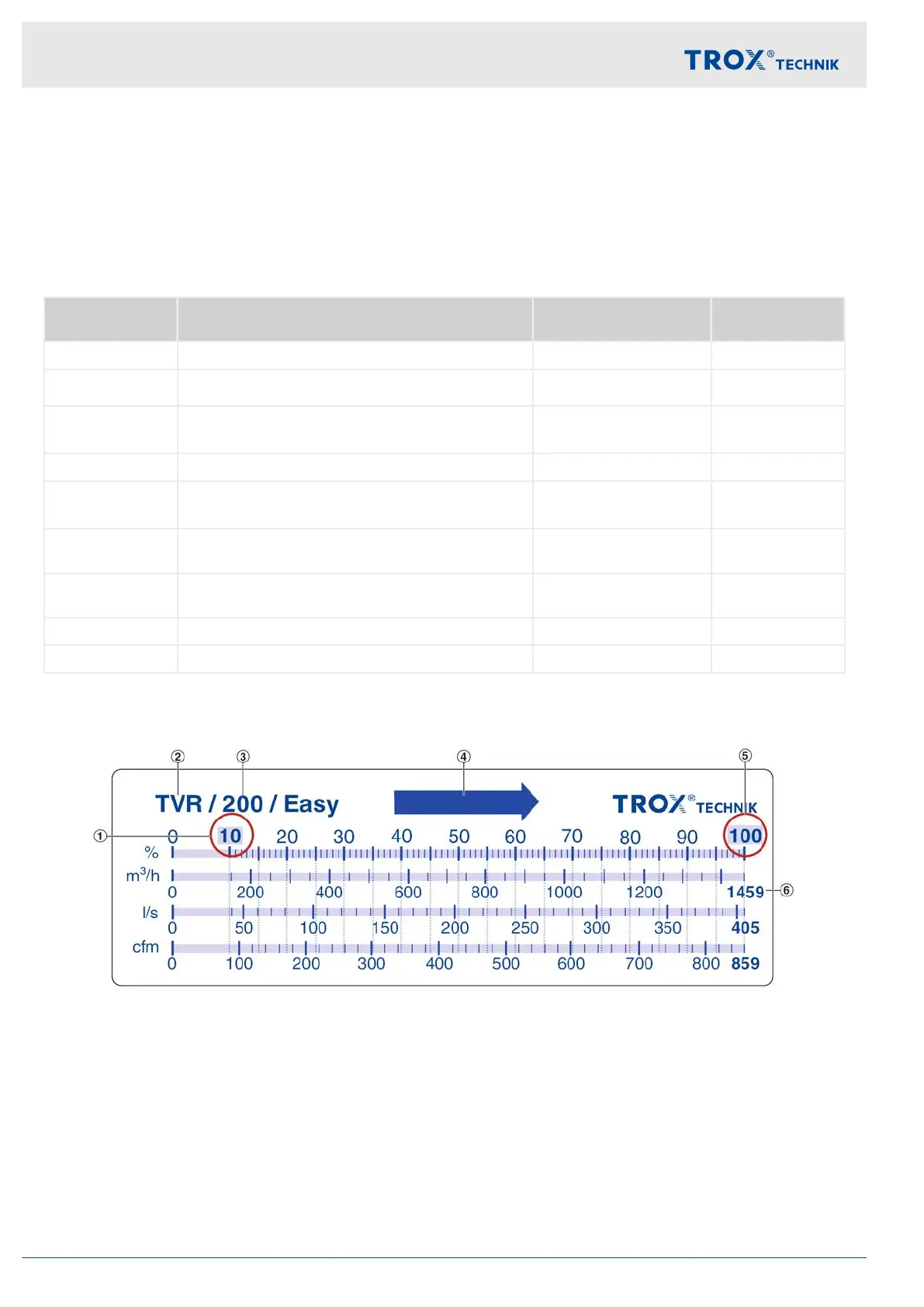
Fig. 21: Scale sticker example TVR/200/Easy
1 Minimal adjustable volume flow rate
2 Type of controller, here e.g. TVR
3 Nominal size
4 Arrow indicating the airflow direction
5 Maximum adjustable volume flow rate
6 Nominal volume flow rate in [m³/h], [l/s] and [cfm]
The scale sticker serves as an aid for setting the volume flow control range. The scale is individual for the combina-
tion of control unit, nominal size and mounted control component.
The grey shaded percentages (1 and 5) document the usable control range of the respective V
AV terminal unit type.
The right edge of the scale at 100% documents the respective nominal volume flow rate in [m³/h], [l/s] and [cfm].
The percentages thus represent the ratio of the respective volume flow rate to the nominal volume flow rate.
Commissioning and operation
Setting of the control component > Volume flow rate scale
Easy control component for VAV terminal units22