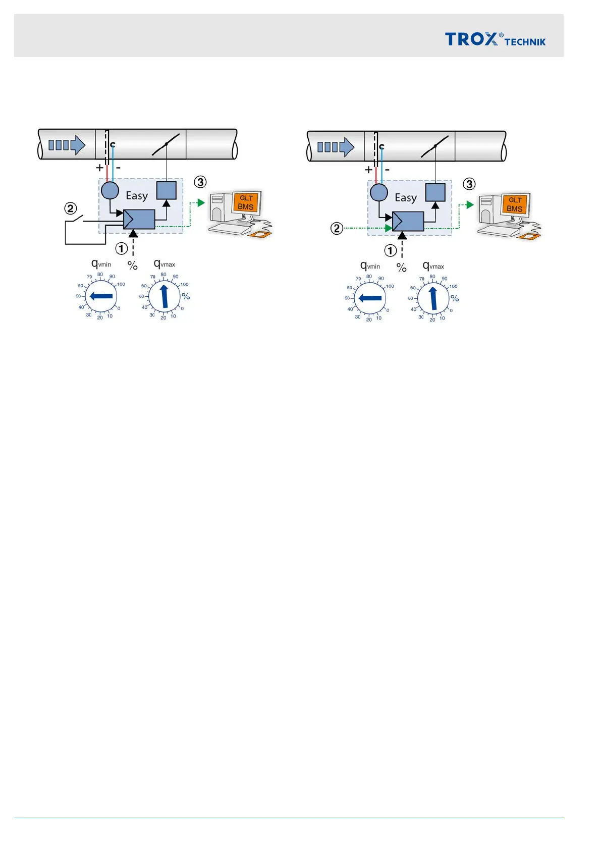
Operation with two setpoint values (min./max.
switching)
Fig. 8: Min./max. switching
1 Volume flow rate setpoint value specification (q
vmin
and q
vmax
)
2 Switch or relay for switching between q
vmin
and q
vmax
3 Actual value volume flow rate as 0–10 V DC signal,
e.g. to the central BMS
The constant values (v
min
and v
max
) set on the rotary
potentiometer can be activated alternately via volt-free
switch contacts. Switching is accomplished by switches
or relays, e.
g., day/night switching.
3.5.2 Operation with variable volume flow
rate setpoint value
Fig. 9: Variable volume flow control
1 Volume flow rate limit specification (q
vmin
and q
vmax
)
2 Control signal 0–10 V DC at terminal w as setpoint
value input, e.g.
from room temperature controller or
DCC outstation or similar
3 Actual value volume flow rate as 0–10 V DC signal,
e.g. to the central BMS
For the use of variable volume flow rate setpoint values,
the specification of an electrical control signal must be
made by a higher-level controller (e.g. room temperature
controller, air quality controller, central building manage-
ment system, etc.). If the input signal is changed, the
controller adjusts the volume flow rate to the new set-
point. The variable volume flow rate is limited to a min-
imum and maximum volume flow rate value,
Ä
Chapter
3.6 ‘Characteristics’ on page 16 .
Override control
The constant or variable control can be disabled by
override controls, e.g. when the window is open, a
window switch stops ventilation of the room by closing
the damper blade.
Further application examples:
Circuits for quick ventilation (q
vmax
)
Opening the damper blade
Structure and functional description
Operating modes > Operation with variable volume flow rate setpo...
Easy control component for VAV terminal units14