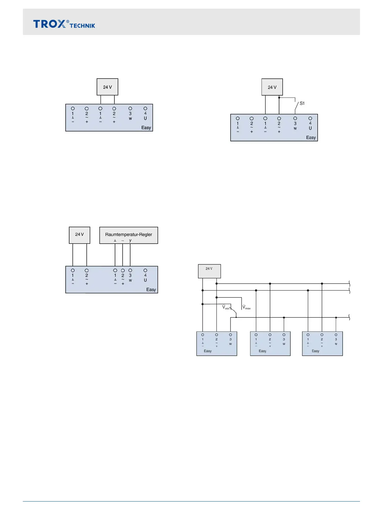
Control constant volume flow rate q
vmin
Fig. 14: Constant volume flow rate q
vmin
After applying the 24 V supply voltage, the controller
throttles the volume flow rate to the value set on the
q
vmin
potentiometer
. A setpoint value signal is not
required. The current actual value volume flow rate can
be tapped at the terminal (U).
Variable volume flow control q
vmin
…q
vmax
Fig. 15: Variable volume flow control
If the volume flow rate is to be specified by a higher-
level controller (e.
g. for room temperature, air quality or
a DDC outstation), its 0–10 V DC output must be con-
nected by at least 2 wires (terminals 1 and 3) to the ter-
minals for the control signal (w) of the Easy controller in
accordance with the connection diagram. With a
common 24 V supply voltage, it should be noted that
terminal 1 on the Easy controller is also the ground for
the control signal.
Switching between volume flow rates q
vmin
and q
vmax
Fig. 16: Switching between volume flow rates q
vmin
and
q
vmax
If the volume flow rate between two constant values can
be switched (e.
g., day/night switching), it is possible to
switch over between the volume flow rate setpoint
values specified by the q
vmin
and q
vmax
potentiometers
using an on-site volt-free switch contact.
Switch S1 open - q
vmin
Switch S1 closed - q
vmax
Parallel connection
Fig. 17: Parallel connection
If multiple Easy controllers are to be switched simulta-
neously with a switch contact between q
vmin
and q
vmax
,
the S1 switch must be designed as a changeover
switch, and the contact for q
vmin
operation must be con-
nected to the ground (terminal 1)
Wiring
Connection diagrams
Easy control component for VAV terminal units 19