This document is an operator's manual for a Troy-Bilt Two-Stage Snow Thrower, specifically covering the Storm 2410, 2420, 2620, 2625, 2840, 2890, and 3090 models. It provides comprehensive instructions for safe operation, assembly, setup, maintenance, service, troubleshooting, and warranty information.
The snow thrower is designed to clear snow from various surfaces. Its two-stage design efficiently collects snow with an auger and then expels it through a discharge chute using an impeller. The manual emphasizes the importance of reading and understanding all safety rules and instructions before operating the machine to prevent personal injury or property damage.
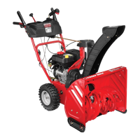
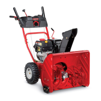
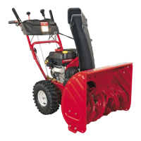
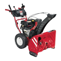
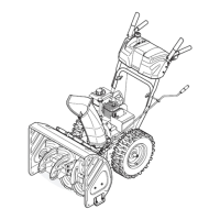
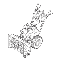
Function Description:
The Troy-Bilt Two-Stage Snow Thrower is a power-driven machine used for removing snow. It features an engine that powers both the auger/impeller system and the wheel drive, allowing the operator to propel the machine and clear snow simultaneously. The augers rotate to gather snow into the auger housing, where the impeller then forcefully discharges it through the chute assembly. The machine is equipped with various controls to manage its operation, including a shift lever for speed and direction, an auger control to engage the snow-throwing mechanism, and a drive control for wheel propulsion. Some models also include steering trigger controls for enhanced maneuverability and heated grips for operator comfort in cold weather.
Usage Features:
- Starting and Stopping: The manual directs users to the engine operator's manual for detailed instructions on starting and stopping the engine. Before starting, it's crucial to ensure all control levers are disengaged and the area is clear of obstructions.
- Engaging Drive: To move the snow thrower, the shift lever is placed in one of the six forward (F) or two reverse (R) positions, and the drive control is squeezed against the handle. Releasing the drive control stops the machine's motion.
- Engaging Augers: The auger control, located on the left handle, is squeezed to engage the augers and begin snow throwing. Releasing it stops the augers.
- Steering (Models with Steering Trigger Controls): For models equipped with steering triggers, squeezing the right control turns the machine right, and squeezing the left control turns it left. This feature enhances maneuverability, especially in open areas.
- Chute Directional Control: The chute assembly can be adjusted to control the direction and distance snow is thrown. Depending on the model, this can be a standard chute directional control, a 2-way control, or a 4-way control. The 4-way control allows for both horizontal rotation and vertical tilt of the chute.
- Skid Shoe Adjustment: Skid shoes are adjustable to suit different surface conditions. They can be raised for close snow removal on smooth surfaces or lowered for uneven terrain like gravel driveways, providing clearance between the shave plate and the ground.
- Chute Clean-Out Tool: A dedicated clean-out tool is provided and fastened to the auger housing. This tool is essential for safely dislodging snow and ice from a clogged chute assembly, preventing operators from using their hands, which could lead to serious injury.
- Heated Grips (If Equipped): For operator comfort, some models feature heated handle grips, activated by a switch on the dash panel. Users are advised to wear gloves and turn off the grips if they become too hot.
- Headlight (If Equipped): A headlight, located on the handle panel, automatically turns on when the engine starts, providing visibility during low-light operation.
- Safety Practices: The manual strongly emphasizes safety, including wearing eye protection, avoiding loose clothing, keeping bystanders away, and never operating the machine under the influence of alcohol or drugs. It also provides specific instructions for safe handling of gasoline and clearing clogged chutes.
Maintenance Features:
- Engine Maintenance: Users are directed to the separate Engine Operator's Manual for specific engine maintenance instructions.
- Shave Plate and Skid Shoes: These components are subject to wear and should be checked periodically and replaced as necessary. Deluxe skid shoes on some models have two wear edges and can be rotated for extended use.
- Lubrication: Regular lubrication is crucial for the machine's longevity. The gear (hex) shaft should be lubricated at least once a season or every 25 hours of operation. The auger shaft also requires lubrication inside the shaft and around spacers and flange bearings. Wheels should be removed and axles coated with multipurpose automotive grease annually. The eye-bolt bushing and spiral of the standard chute directional control (Model 2410) should be lubricated with 3-in-1 oil once a season.
- Tire Pressure: Tires are often over-inflated for shipping. Operators must check and adjust tire pressure according to the manufacturer's recommended psi before operation to ensure proper machine travel and even shave plate wear.
- Shift Cable Adjustment: If the full range of speeds (forward and reverse) cannot be achieved, the shift cable may need adjustment to take up slack.
- Drive Control Adjustment: The drive control cable should have minimal slack when disengaged. If the drive disengages intermittently or the unit does not roll freely when disengaged, the cable may need adjustment.
- Auger Control Adjustment: The auger control cable should also have minimal slack when disengaged. If the auger shows signs of rotation when disengaged, the cable needs adjustment.
- Chute Assembly Adjustment: For models with overhead chute control (2890 and 3090), if the chute fails to remain stationary, the preload can be adjusted by tightening a hex nut. If the chute is difficult to crank, the preload can be decreased by loosening the hex nut. For Model 2410, the chute bracket can be adjusted if the spiral is not fully engaging.
- Chute Control Rod Adjustment: For models 2420, 2620, 2625, and 2840, the chute control rod can be adjusted to ensure proper engagement with the chute rotation assembly.
- Belt Replacement (Auger Belt): Detailed instructions are provided for removing and replacing the auger belt, including steps for accessing the belt and ensuring proper reinstallation. The manual warns against using non-OEM shear pins to avoid damage to the gearbox and voiding the warranty.
- Friction Wheel Inspection and Removal: Instructions are given for inspecting the friction wheel for wear or cracking. For models other than 2890 and 3090, steps for removing and replacing the friction wheel or its rubber ring are provided. Special tools may be required for drive belt and friction wheel rubber replacement on some models, recommending professional service or contacting customer support.
- Off-Season Storage: For storage longer than 30 days, the engine should be run until the fuel tank is empty. The machine should be lubricated, stored in a clean, dry area, and rustproofed with light oil or silicone if stored in an unventilated area. The exterior should also be cleaned.
- Troubleshooting Guide: A comprehensive troubleshooting table helps diagnose common issues, such as engine failure to start, erratic running, overheating, excessive vibration, loss of power, failure to propel, failure to discharge snow, and chute rotation problems, along with suggested remedies.