AIS-CTRX Class B AIS Transponder Manual
INSTALLING THE AIS-CTRX UNIT
WARNING: Do not connect the AIS-CTRX unit to mains (line) AC electrical supply, as an electric
shock or fire hazard could result.
CAUTION: Do not connect the AIS-CTRX unit to a DC supply exceeding 15.6 V or reverse the supply
polarity. Damage to the unit may result.
CAUTION: The AIS-CTRX unit is designed for operation in the temperature range -25 °C to +55 °C.
Do not install (or use) the AIS-CTRX unit in environments which exceed this range.
CAUTION: do not install the AIS-CTRX unit in an environment where it can be subject to excessive
exposure to water.
Electrical Connections
Warning:
Only the RF,
data and power cables
provided with the AIS-
CTRX unit should be used
to connect antennas,
power and display devices
so as to maintain the
integrity of the enclosure.
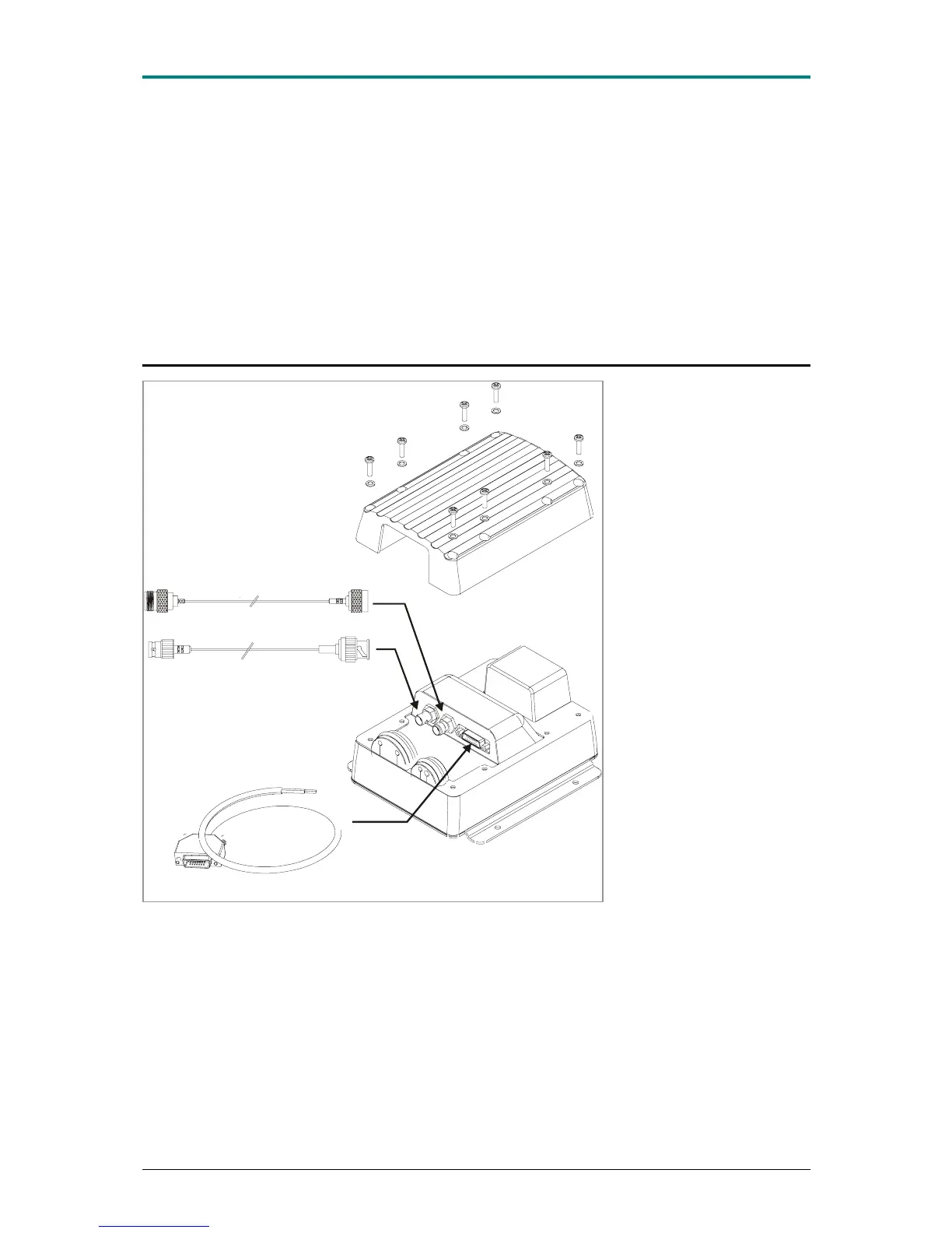
Power Cable (or Power and Data Cable)
GPS Antenna Cable
VHF Antenna Cable
Please see the drawings
section of this manual for
details of the power, data and
RF cables supplied
Remove the top of the
transponder unit (eight
screws) as shown.
Using the two co-axial leads
supplied connect the down-
lead from a VHF antenna to
the VHF antenna port and
connect the down-lead of a
GPS antenna to the GPS
antenna port.
Please see Appendix A for
recommendations on
antennas and antenna
installation.
If an external display unit (chart plotter, PC etc) is to be used connect the supplied power and data
interface cable to the Power / NMEA port.
If an external display unit is
not to be used connect the supplied power only interface cable to the
Power / NMEA port.
Locate the RF, power and/or data cables into the rubber grommets pushing them firmly to the base of
each slit. Each cable is pushed into the grommet slit which lies directly in front of the connector the
cable is connected to.
Replace the top of the transponder unit taking care to seat the cable grommets and the lid seal
correctly. Do not over-tighten the fixing screws.
1.1E 19 LD2103