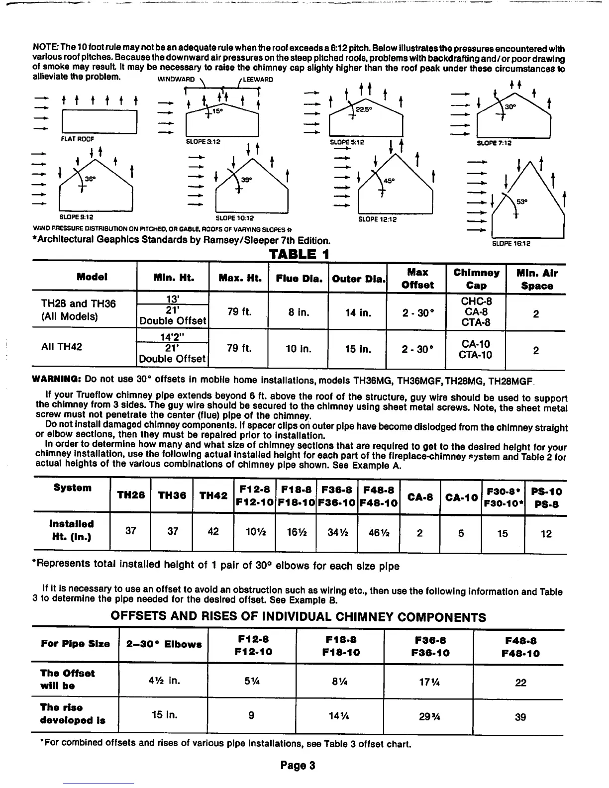
NOTE:
The10footrulemaynotbeanadequaterulewhenthe roofexceedsa6:12pitch.Belowillustratesthe pressuresencountered
with
various
roof
pitches.
Becausethe
downward
airpressuresonthesteep
pitched
roofs,
problems
with
backdrafting
and/or poor
drawing
of smoke may result It may be necessary to raise the chimney
cap
slighty higher than the roof peak under these circumstances to
allieviate the problem.
windward
\ /leewaro
A.
1
r
ZZ
♦
t t t i i — t
Liij
FLAT
ROOF
i36°
SLOPE
9:12
SLOPE
10:12
WIND PRESSURE DISTRIBUTION ON PITCHE0.OR GABLE.ROOFSOFVARYING SLOPES*
♦Architectural
Geaphics
Standards
by
Ramsey/Sleeper
7th Edition.
TABLE
1
SLOPE
16:12
Model
Mln.
Ht.
Max.
Ht.
Flue
Dla.
Outer
Dia.
Max
Offset
Chimney
Cap
Min.
Air
Space
TH28
and
TH36
(All
Models)
13'
79
ft.
8
in.
14
in.
2-30°
CHC-8
CA-8
CTA-8
21'
Double
Offset
2
14'2"
79
ft.
10
in.
15
in.
2-30°
CA-10
CTA-10
All
TH42
21'
Double
Offset
2
WARNING:
Do
not use 30° offsets in mobile home installations, models
TH36MG,
TH36MGF.TH28MG,
TH28MGF
If
your
Trueflow
chimney
pipe
extends
beyond
6
ft.
above
the
roof
of
the
structure,
guy
wire
should
be
used
to
support
the
chimney
from
3 sides.
The
guy
wire
should
be secured to the
chimney
using
sheet
metal
screws.
Note,
the sheet
metal
screw
must
not penetrate
the
center
(flue) pipe of the chimney.
Do
not
install
damaged
chimney
components.
If
spacer
clips
oh
outer
pipe
have
become
dislodged
from
the
chimney
straight
or elbow sections, then they
must
be repaired prior to installation.
In
order
to
determine
how
many
and
what
size
of
chimney
sections
that
are
required
togettothe
desired
height
for
your
chimney
installation,
usethe
following
actual
installed
height
for
each
part
ofthe
fireplace-chimney
eystem
and
Table
2
for
actual heights of the various combinations of chimney pipe shown.See
Example
A.
System
Installed
Ht.
(In.)
TH28
37
TH36
37
TH42
42
F12-8
F12-10
10V2
F18-8
F18-10
16Y2
F36-8
F36-10
341/2
F48-8
F48-10
461/2
CA-8
CA-10
F30-8*
F30-10*
15
PS-10
PS-8
12
•Represents
total
installed
height
of 1
pair
of
30°
elbows
for
each size
pipe
If
it
is
necessary
tousean
offset
to
avoid
an
obstruction
such
as
wiring
etc.,
then
usethe
following
information
and
Table
3 to determine the pipe needed for the desired offset. See
Example
B.
OFFSETS
AND
RISES
OF
INDIVIDUAL CHIMNEY
COMPONENTS
For
Pipe
Size
2-30°
Elbows
F12-8
F12-10
F18-8
F18-10
F36-8
F36-10
F48-8
F48-10
The
Offset
will
be
41/2
in.
51/4
8V4
17V4
22
The
rise
developed
is
15
in.
9
14V4
29%
39
•For combined
offsets
and
rises of various pipe installations,
see
Table 3
offset
chart.
Page
3