Component Glossary
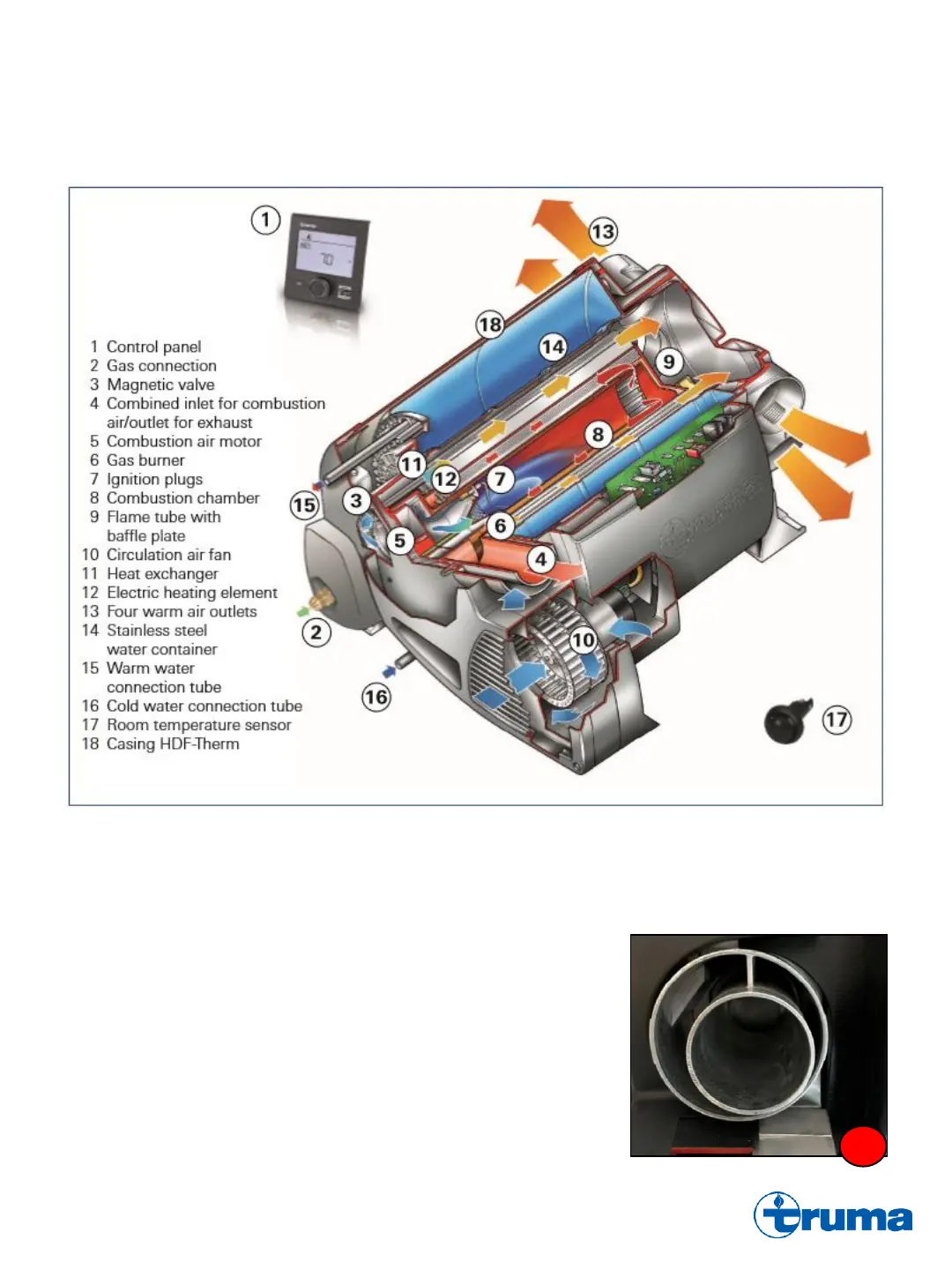
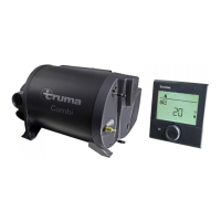
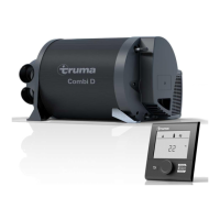
1. CP Plus Control Panel : Operation and programming of the Truma Combi is controlled by the CP Plus Control Panel.
Powered by a separate 12VDC source from the Combi and protected with a 1A in-line fuse. Connected to the Truma
Combi PCB by a data cable. A W 255 H error code will be displayed on the CP Plus in the event of a connectivity issue
with the Combi PCB.
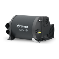
2. Gas Connection : 5/8” flared male inlet gas supply connection. Operating inlet pressure: 11-13” WC (27.4-32.4 mBar).
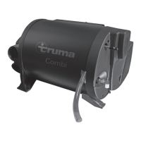
3. Magnetic Gas Valve : Supply gas pressure to the combustion chamber is
controlled and regulated by the magnetic gas valve. Depending on the level of
combustion required, the (2) magnetic gas valve solenoids will open or close to
provide 7,500 BTU, 14,300 BTU, or 20,400 BTU (Comfort models only) of
propane to the combustion chamber. Includes a test nozzle for obtaining manifold
pressure: 9.5-11” WC (23.7-27.4mBar).
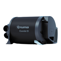
4. Combined Inlet for Combustion Air/Outlet for Exhaust : Connection for
Combustion Air Inlet tube (80mm) and Exhaust Outlet tube (55mm). Both tubes
terminate on the sidewall of the RV through the Wall Cowl. Combustion air is
pulled into the Combi and exhaust air is pushed out by the Combustion Air Motor.
A damaged or compromised Exhaust Outlet tube may result in exhaust air mixing
with fresh combustion air, leading to combustion failures.
4