Additional Components
G H
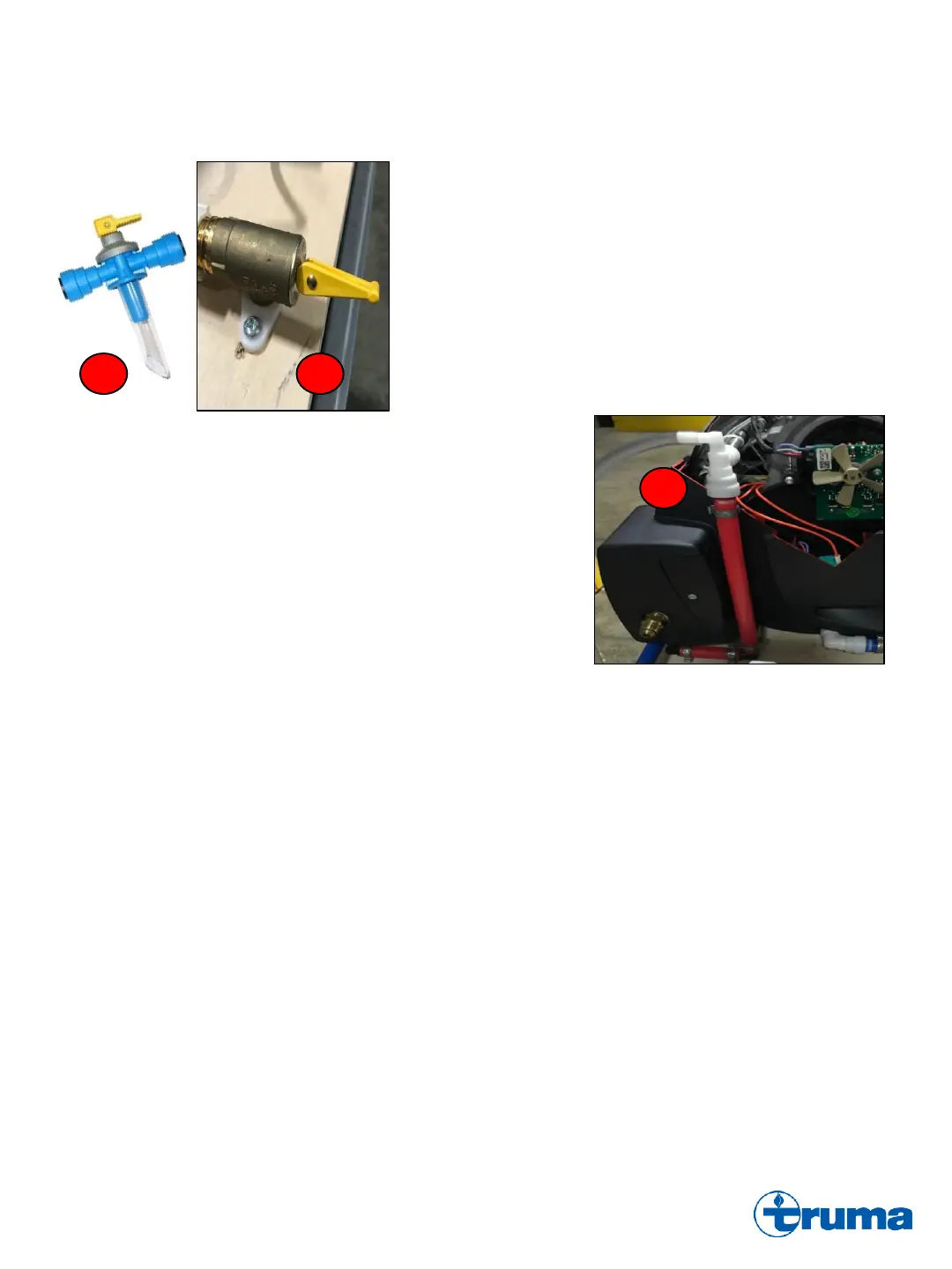
G. Drain Valve (Previous version) : Shown in the “closed” position,
the drain valve is installed on the cold water inlet of the Combi and
is used to drain the Water Container when placed in the “open”
position. In addition to a manual drain, it also automatically opens
when pressure above 51psi are present.
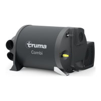
H. Drain Valve (Current version) : Shown in the “open” position, the
current drain valve model replaced the previous version in 2017.
In addition to a manual drain, the Drain Valve also features an
automatic pressure relief safety that activates when pressures
above 66.25psi are present.
I. Wall Cowl (Not pictured) : A concentric vent located on the sidewall of
the RV, the Wall Cowl is the entry point for fresh combustion air into the
Combustion Air Inlet Tube, and the exit for exhaust air through the
Exhaust Outlet Tube.
J. Gas Shutoff Switch (Not pictured) : The Gas Shutoff Switch, located
above the 12VDC PCB, controls 12VDC power to the Gas Valve. Turning
the Gas Shutoff Switch to the “OFF” position will deenergize the Gas
Valve and result in one of the following fault codes when the Combi goes
to fire: E 112 H, E 121 H, E 122 H, E 202 H, E 211 H, and/or E 212 H.
See “Fault Codes: Further Details”.
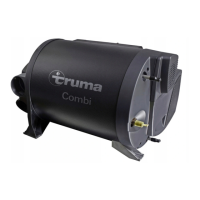
K. Warm Water Connection with Aeration Valve : The hot water plumbing
connection to the Warm Water Outlet of the Combi. Elbow fitting consists
of an Aeration Valve with a gravity-fed check valve to ensure that all
2.64gal (10 liter) of water is drained from the Water Container when the
Drain Valve is opened. Must be installed so that hot water plumbing line
flows in a vertical direction (see picture K for proper install). A Combi that
doesn’t completely drain could be evidence of an Aeration Valve issue.
K
Step 1.
Once the Combi receives a call for heat from the CP Plus, a Green LED will illuminate on the PCB. The Combustion Air Motor
and the Circulation Air Fan* will run for 30 seconds to purge the system. The Combustion Air Motor and Circulation Air Fan*
will ramp up to operating level 2 (14,300BTU) fan speeds right before the start of Step 2.
Step 2.
Once the Combustion Air Motor and Circulation Air Fan* has reached operating level 2 speeds, a yellow LED will illuminate on
the PCB. The Magnetic Gas Valve will open at the same time that the Direct Spark Ignitor is energized and begins sparking.
Step 3.
After the three ingredients for combustion (air, fuel, and spark) have been introduced to the Combustion Chamber, the burner
flame will activate. Once the flame presence has been proven by the Flame Sensor, a red LED will illuminate on the PCB.
Heat from the Gas Burner will then make its way into the Water Container and/or be distributed throughout the RV via the duct
work by the Circulation Air Fan*.
* If the Combi is strictly in water heating mode and not furnace mode, the Circulation Air Fan will not operate. The purpose of
the Circulation Air Fan is to operate while the Combi is in furnace mode to distribute hot air throughout the RV via the ducting
system. However, it’ll also act as a cooling device for the Combi in the event of an overheat situation in any operational mode.
Sequence of Operations