20
In order to maintain the validity of the General Operating
Permit (ABE), the provided factory plates (f) must be at-
tached on the left and right sides of the cross strut next to the
drive unit retaining plates.
f
f
Fig. 18
Loosely attach the drive units to the lateral bar. The bolts (lock
nuts) must be no more than finger-tight.
Nut M8 (4 x)
M8 x 30 (4 x)
Fig. 19
Place the drive units with the crossbar and attachment set (b)
onto the vehicle frame and screw tight with the two screws
(c) so that it is just possible to slide along the frame.
The gripper (a) must lie completely flat on the chassis
frame.
b
c
a
Fig. 20
b
Fig. 21
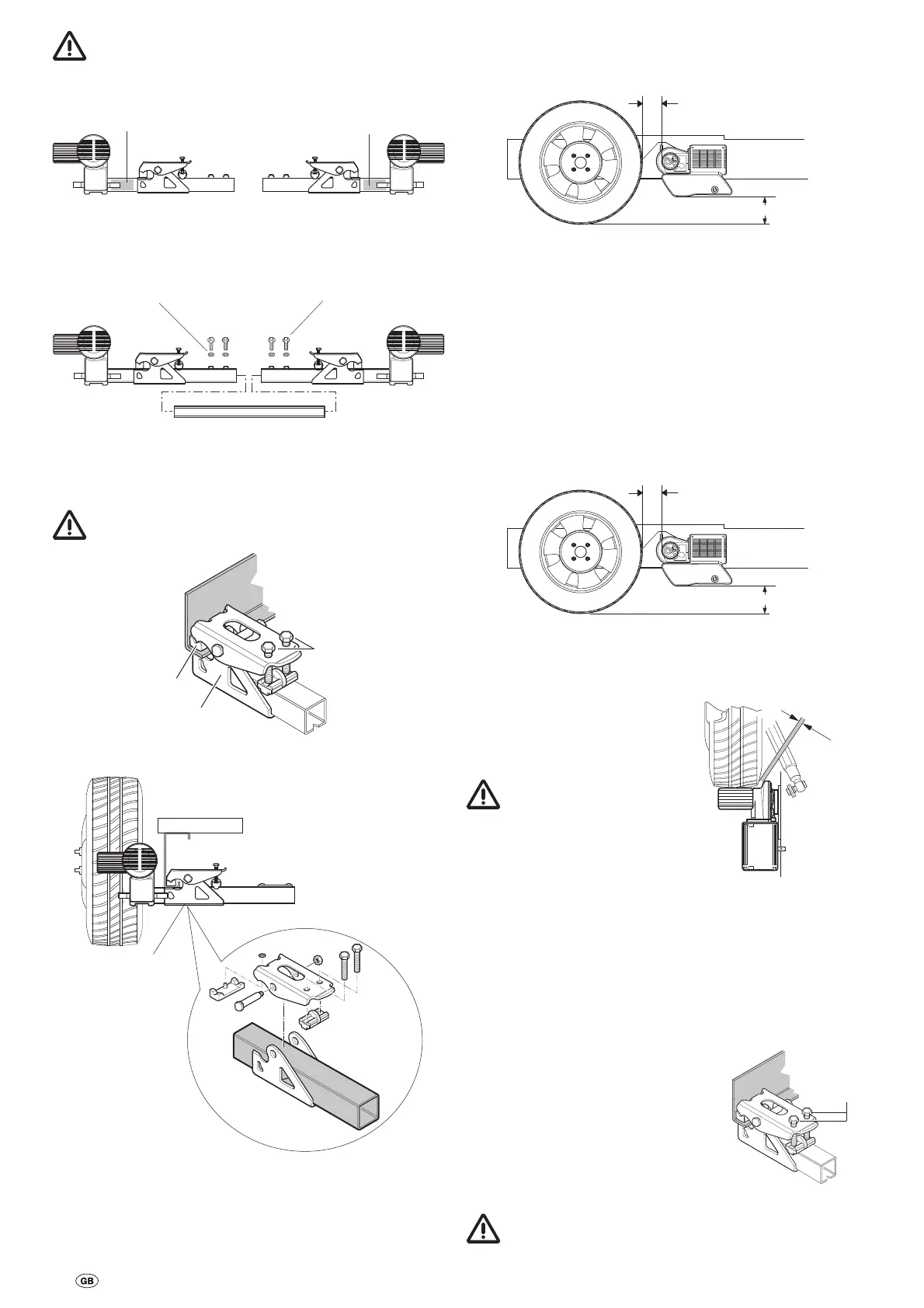
Position the drive rollers so that they are approximately at the
height of the wheel hub / centre.
20 mm
min. 110 mm
Fig. 22
If there is a height difference, Truma has 30 mm and 60 mm
spacer sets in its accessory program to compensate the
height difference.
Spacer set 30 mm, part no. 60030-95000,
Spacer set 60 mm, part no. 60030-95100.
Ensure there is enough clearance to the ground
(min. 110 mm).
The correct distance can be set between the tyre and the
roller (20 mm) with the provided spacer by sliding the (disen-
gaged) drive units in the longitudinal direction. The movable
middle tube makes it possible to adapt to the width of the
frame.
20 mm
min. 110 mm
Fig. 23
Slide drive units in lateral direction so that the maximum
amount of tyre tread is covered.
Ensure that there is adequate
clearance between the gearbox
and the tyre / shock absorber so
that they do not touch.
The minimum clearance
with the drive units
engaged in is 10 mm.
min.
10 mm
Fig. 24
After positioning correctly, slightly tighten the screws (c) of
the attachment set and then check the defined distances
again. During this, the weight of the caravan must be on the
tyres.
Move sliding middle tube to a central position (e.g. measure
at open side of middle tube with a pocket rule), tighten the
4 bolts (20 Nm) and secure the locknuts.
Recheck that the distance to the tyres
is 20 mm (when the wheels are under
load). Then tighten the 2 screws of
the attachment set (M10) alternately
with a torque of 25 Nm.
25 Nm
Fig. 25
The screws are coated with a sealant and may therefore
only be screwed in once.