22
ELECTRICAL CONNECTIONS
2
3
4
Hot Water Outlet Connection (Red Arrow)
Next, connect the outflowing Hot Water Supply main to the Outlet connection, indicated by the Red “Outlet
Water” tag. This is accomplished in a manner identical to connecting the inlet supply.
Turn on the water supply to the system. Open a hot water tap in the house to allow water to flow.
NOTE: Outflowing water will be cold at this point of installation. Water will not flow hot until electrical supply is
connected. Verify that the inlet and outlet connections are leak-free, both with water flowing and with the water
flow stopped. Maintain water pressure and check for leaks for a minimum of ten (10) minutes. If a slight leak is
noted at either of the stainless steel flexible line connection points, carefully tighten further with both wrenches
as noted above.
Pressure Relief Valve
Note that a temperature pressure and relief safety valve is not required according to national plumbing codes
as instantaneous water heaters are not considered pressure vessels. The trutankless comes equipped with a
mechanical thermal cut out and the copper manifold is not defined as a pressure vessel according to ASME. If
your water lines are plastic piping or tubing (PVC,PEX, Etc.), a pressure relief valve rated to equal or less than the
PSI rating of the tubing should be installed.
T&P valve may be required to meet installation codes in your area. If one is required, install the pressure relief
valve branched o the hot outlet side.
The trutankless TR/TC unit plumbing connections are now completed.
ABOVE INFORMATION IS MEANT ONLY AS A GUIDELINE AND SHOULD NOT BE RELIED UPON TO GUARANTEE SAFETY OF INSTALLATION OR CODE
COMPLIANCE. ELECTRICAL WIRING SHOULD ONLY BE PERFORMED BY A QUALIFIED AND PROPERLY LICENSED CONTRACTOR. PLEASE ENSURE YOUR
TRUTANKLESS MODEL IS PROPERLY WIRED ACCORDING TO LOCAL AND NATIONAL ELECTRICAL CODES. IMPROPER ELECTRICAL INSTALLATION COULD
CAUSE DAMAGE TO PROPERTY AND MAY RESULT IN PERSONAL INJURY OR DEATH.
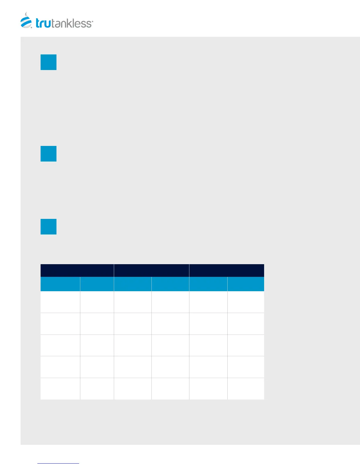
Model
Maximum
Amperage
Minimum
Breaker Size
Minimum
Wire Size
Minimum
Breaker Size
Minimum
Wire Size
TR36/TC33
160
2 x 80 Amp
2-Pole Breakers
4 x #4 Ga.
Copper
TR29/TC25
120
2 x 60 Amp
2-Pole Breakers
4 x #6 Ga.
Copper
1 x 125 Amp
2-Pole Breakers
2 x #2 Ga.
Copper
TR24/TC21
100
2 x 50 Amp
2-Pole Breakers
4 x #6 Ga.
Copper
1 x 100 Amp
2-Pole Breakers
2 x #2 Ga.
Copper
TR20/TC17
80
2 x 40 Amp
2-Pole Breakers
4 x #8 Ga.
Copper
1 x 80 Amp
2-Pole Breakers
2 x #4 Ga.
Copper
TR15/TC13
60
2 x 30 Amp
2-Pole Breakers
4 x #8 Ga.
Copper
1 x 60 Amp
2-Pole Breakers
2 x #6 Ga.
Copper
ELECTRICAL REFERENCE OPTION 1 OPTION 2