INSTALLATION AND OPERATION GUIDE
23
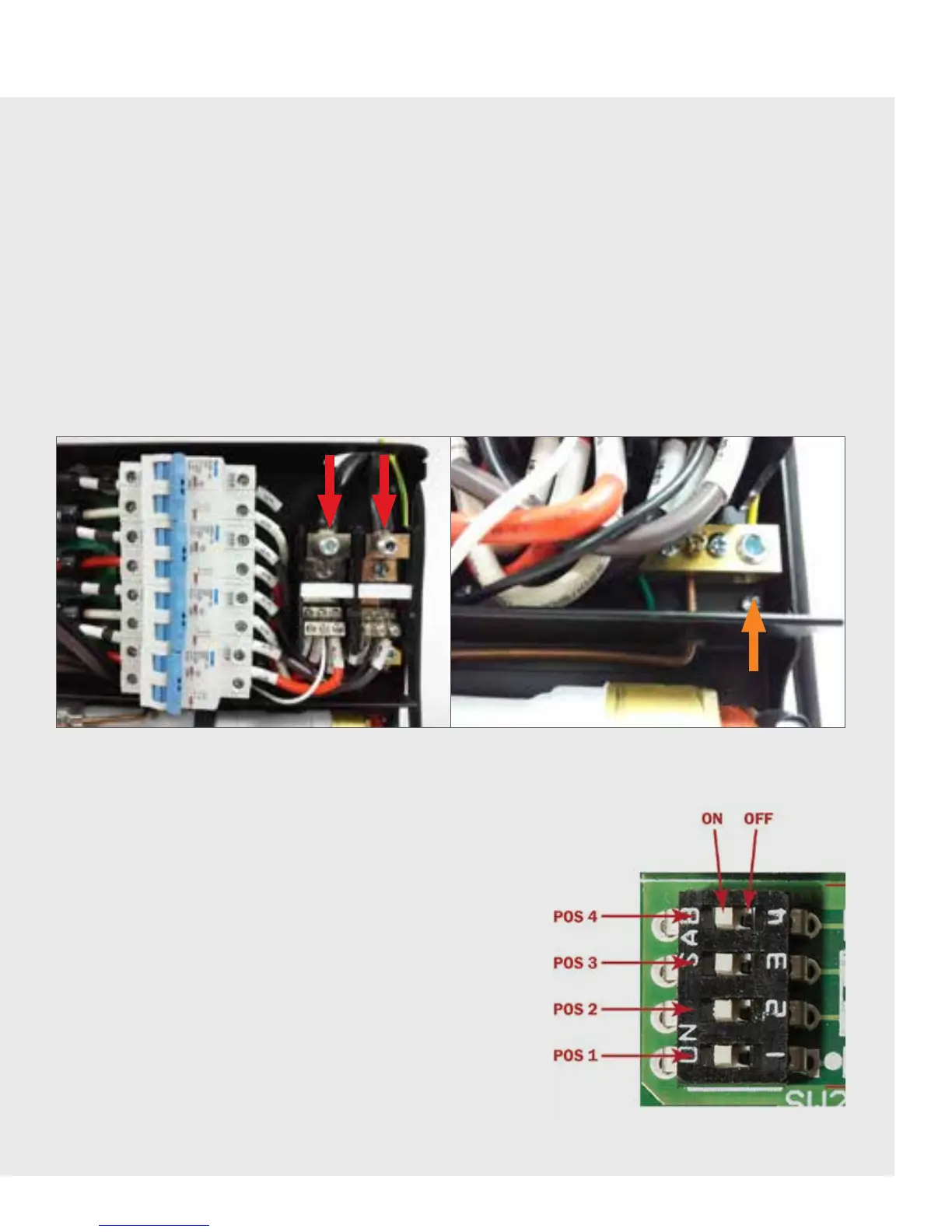
Figure 5. Wiring Connections: L1, L2 (Red Arrow) & Ground (Orange Arrow)
NOTE: Electrical service connection to the unit must be performed by a licensed contractor in accordance with all
applicable National Electric Safety Codes, and all state/provincial and local electrical codes.
WARNING: This heating apparatus is an electrically powered high voltage and high current device. It is intended to be
installedby a qualified and licensed contractor only. Failure to install this unit in accordance with all applicable codes and
requirements may result in personal injury or death.
WARNING: Make sure the main power is OFF before proceeding with the electrical serviceconnection to the system.
NOTE: We strongly recommend the use of copper conductors only.
NOTE: Electrical connections should be made ONLY aer the water system is connected and is tested to be leak-free; all
appropriate fittings are installed; and the required AWG copper wires have been routed to the trutankless
MODEL BR/BCWater Heater.
PRODUCT MODEL SETTINGS
IMPORTANT: IDEAL PERFORMANCE OF THE TRUTANKLESS
SYSTEM DEPENDS ON COMPLIANCE WITH THIS SECTION.
The DIP switch positions determine the performance parameters of
the unit model. To ensure proper installation and system operation,
the unit must be configured using the dip switches settings specified
in figure below and pictured in the table on the following page.
Following these instructions and properly setting the DIP switches
at installation is extremely critical to the proper functioning of
the system and willensure ideal temperature rise and flow rate
maximums.