89
Appendix C
Wiring Information
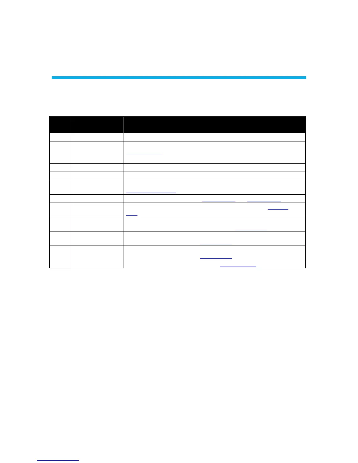
Back Panel Wiring
Input/Output/
Communication
24 VAC to power Digital Interface Module (DIM).
0 to 10 VDC fume hood exhaust control signal. See menu item
CONTROL SIG
Not used on fume hood monitor.
LONworks
®
/BACnet
®
MS/TP communications (optional)
RS-485 communications to building management system (Modbus
®
or N2)
0 to 10 VDC/4 to 20 mA analog output signal. See menu item
ANALOG OUT TYPE.
Alarm Relay B. See menu items RELAYS OUT and RELAY SEL B.
Alarm Relay A. Low face velocity/flow alarm. See menu item RELAYS
OUT.
Non-powered input #1. Accepts sash sensor, sash switch, emergency
switch or night setback switch. See menu item INPUT SEL 1.
Non-powered input #2. Accepts sash switch, emergency switch or night
setback switch. See menu item INPUT SEL 2.
Non-powered input #3. Accepts sash switch, emergency switch or night
setback switch. See menu item INPUT SEL 3.
0 to 10 VDC Flow input. See menu item FLOW DEVICE.