AM signals form the PIN 5 of IC1 were tapped with CR34 and amplified two-stage amplifier QR5,6 is a
a first 455KHz amplifier.
DR3 is a detector diode witch produce audio signal as well as negative DC voltage fir AGC action.
The negative voltage laso provides forward biasing to the mitter of ANL clipping TR QR7.
The biasing voltage has a time constant determined RR44 and CR54.
Therefore any sharp negative going pulse from DR3 will back bias QR7 and clipped.
The way to recover the AM information audio is envelope detector.
** Test Equipment Setup and Alignment Instructions
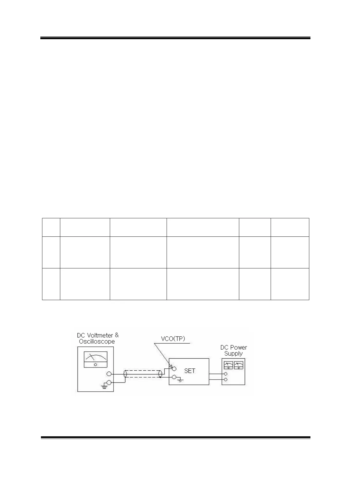
5-1. VCO voltage adjustment
5-1-1. Required Test Equipment
1) DC power supply : 13.8VDC / 3A
2) DC Voltmeter or Oscilloscope
3) RF attenuator (30dB)
5-1-2. Alignment Procedure
Step Test Item UUT setting Equipment setting
Alignment
point
Spec.
1
RX VCO voltage Channel: CH1
UUT: RX condition
Others: Don’t care
Measure the DC voltage
on the VCO test point
LV1 1.8~2.1
Adjustment
(VDC)
2
TX VCO voltage Channel: CH1
UUT: TX condition
Others: Don’t care
Measure the DC voltage
on the VCO test point
LV1 1.5~2.5
Adjustment
(VDC)
5-3. Equipment connection
Figure 1