Copyright by Tunturi Oy Ltd 12 All information subject to changes
TUNTURI
SERVICE MANUAL
_____________________________________________________________________________________ Version 1/2000
4.1.2 Replacing the lift motor
The lift motor is loosened both from the frame and the lift arm by removing the axles from these
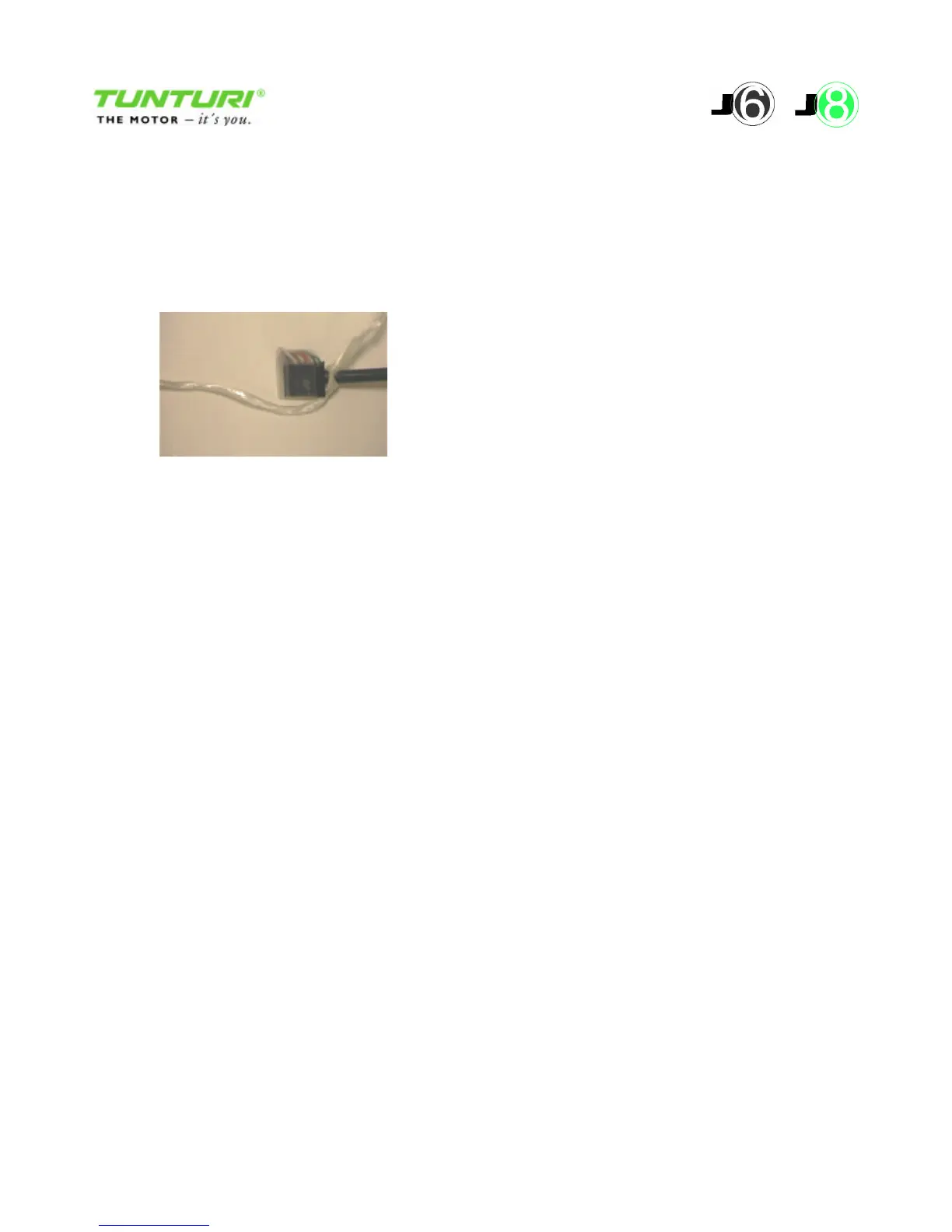
points. Remove the lift motor wire from the connector X2. Tape the wire connector and tie a knot
with string. Pull the string with the wire out of the frame. Using the string, pull the wire of the new
lift motor inside the frame.
4.1.3 Calibrating the lift motor
When the lift motor is replaced, it must be calibrated. The calibration procedure will be
automatically initiated when the page 2 of the Service Menu is selected (see chapter 1.6). Stages of
the calibration:
Cal1 run down Cal2 run up Done ready
The left hand side display shows the goal position 10 / -2 / 0.
The display in the centre shows the stage (Cal1, Cal2, Done).
The right hand side display shows the pulse counter value. The value will be resetted at the end of
stage Cal1, when position 10 (lower limit switch) is reached. At the end of calibration, the elevator
is driven to horizontal, e.g. position 0. The procedure can be re-initiated by pressing + key.
4.2 Lift arm
4.2.1 Replacing the lift arm
The lift arm is attached with screws to the side profiles of the frame. The lift arm can be removed
by opening the screws and loosening the lift motor shaft.
4.2.2 Lift arm rollers
The plastic rollers are locked to their shafts with a locking sleeve.



 To Next Page