e-Boost-40 Instructionse-Boost-40 Instructions
Page 6
PART NUMBER
FG-EBOOST-40FG-EBOOST-40
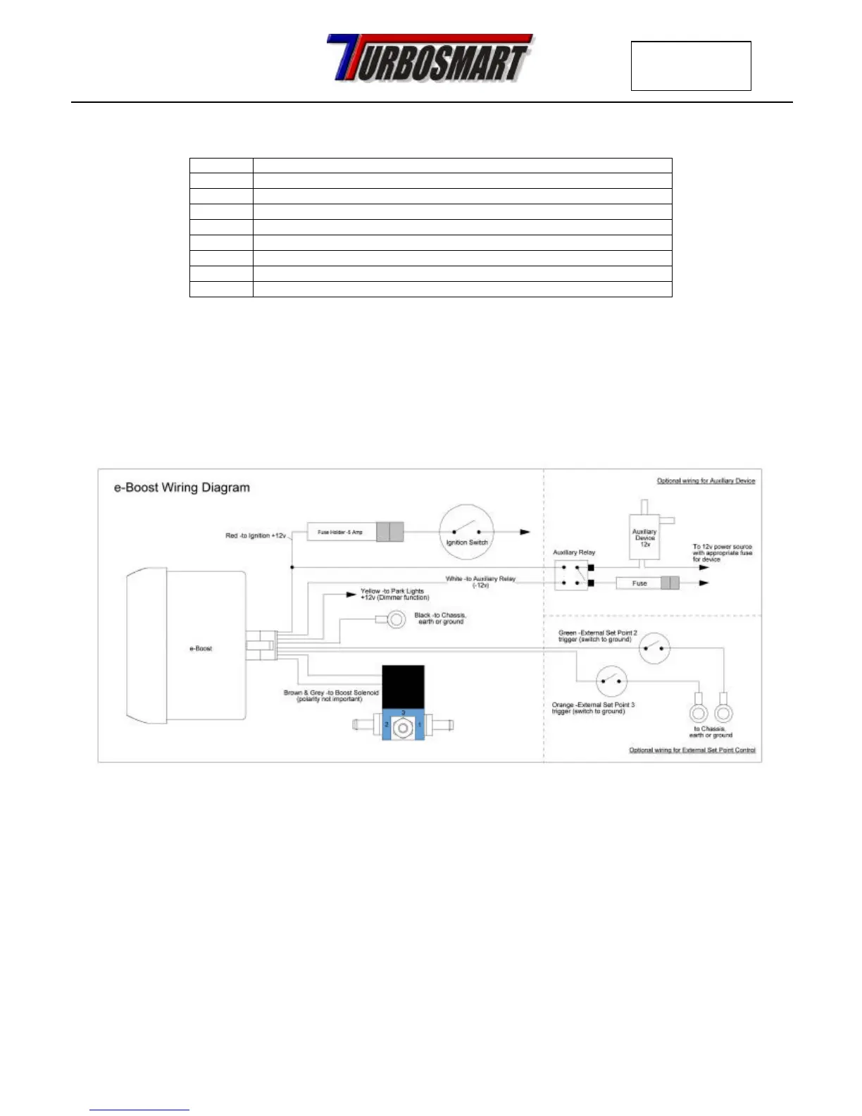
2d. Wiring
Refer to the following table and diagram for detail on wiring the e-Boost.
Wire Connect to
RED
+ 12 Volts switched through ignition – connect via 5 Amp fuse supplied
BLACK
Chassis, earth or ground
GREY
Solenoid wire 1 – connect using wire supplied – polarity not important
BROWN
Solenoid wire 2 - connect using wire supplied – polarity not important
YELLOW
Dimmer circuit + 12 Volts
WHITE
Auxiliary output – switched to ground – see diagram below
GREEN
External set point 2 refer to section 5d
ORANGE
External set point 3 refer to section 5d
Please Note:
All electrical connections must be soldered
The e-Boost must be connected to a 12 volt negative earth electrical system
 Loading...