38 Manchester Series MAN210-FG/MS121/MAN210-HC Rigging Manual
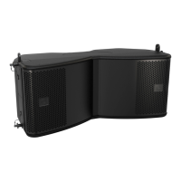
Procedure 5.1 - Attaching the MAN210-FG y grids to the MS121 Subwoofer
1. Perform the previous procedure in Chapter 4: Procedure 4.1 steps 1 to 3,
to attach the MAN210-FG y grid to the MS121 subwoofer.
Note: There is one important dierence: Use rigging pins (1) in the forward
holes of the MAN210-FG y grid to connect to the top links of the subwoofer.
This position will move the y grid rearwards on the subwoofer.
Procedure Description of Work Check
4.1 step 1 to
step 3
Attaching the MS121 Subwoofer to the
MAN210-FG Fly Grid
Double check all pins are correctly inserted, and that the y
grid is securely attached to the top of the subwoofer.
2. Attach a bow shackle or other lifting equipment securely to the single
shackle plate (or Tip Bar) of the MAN210-FG y grid, then attach the hook
and chain. Carefully raise the y grid/subwoofer assembly to a reasonable
working height to allow attachment of the second MAN210-FG y grid.
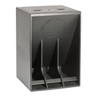
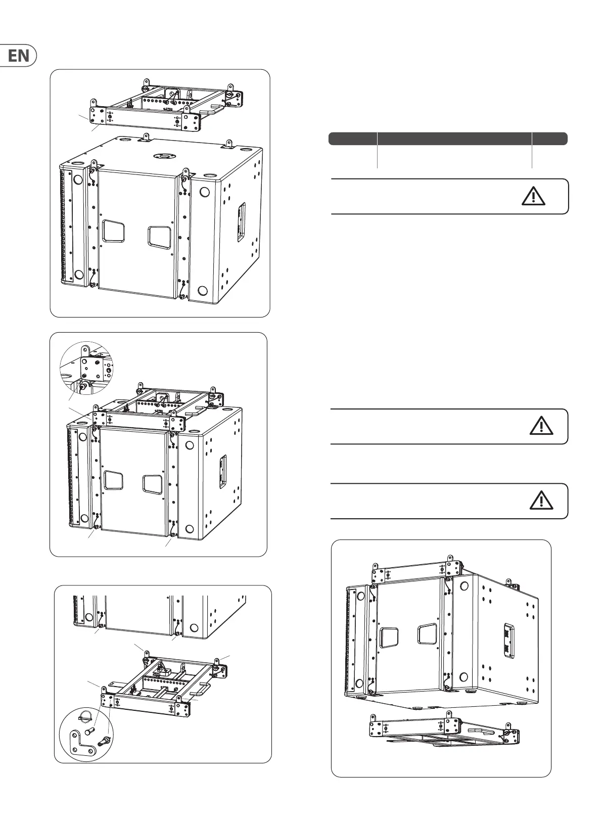
3. Prepare the subwoofer by pulling out the 4 lower rigging pins (2).
4. Prepare the second MAN210-FG y grid by making sure that the L-shaped
links (3) are in the forward position. (This position is important for the lower
y grid, but not the upper y grid). Make sure that the clevis pins (4) are in
the 'corner' hole of the L-shaped links, and that their securing pins (5) are
correctly in position. Secure the rear holes of each L-shaped link with rigging
pins (6). If tted to the second y grid, remove the single shackle plate and
secure it in the stowed position with its 2 pins.
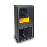
5. Carefully align the top links (3) of the y grid assembly with the
corresponding mounting positions on the bottom of the subwoofer, and
then hold the y grid in place.
Take care not to trap your ngers between components.
6. Insert the subwoofer's 4 lower pins (2) to secure the y grid to the
subwoofer.
Double check all pins are correctly inserted, and that the y
grid is securely attached to the subwoofer.
3
3
3
3
4
6
5
2
2
1
2
2
1
Not used
 Loading...