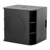
39 Manchester Series MAN210-FG/MS121/MAN210-HC Rigging Manual
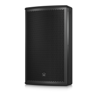
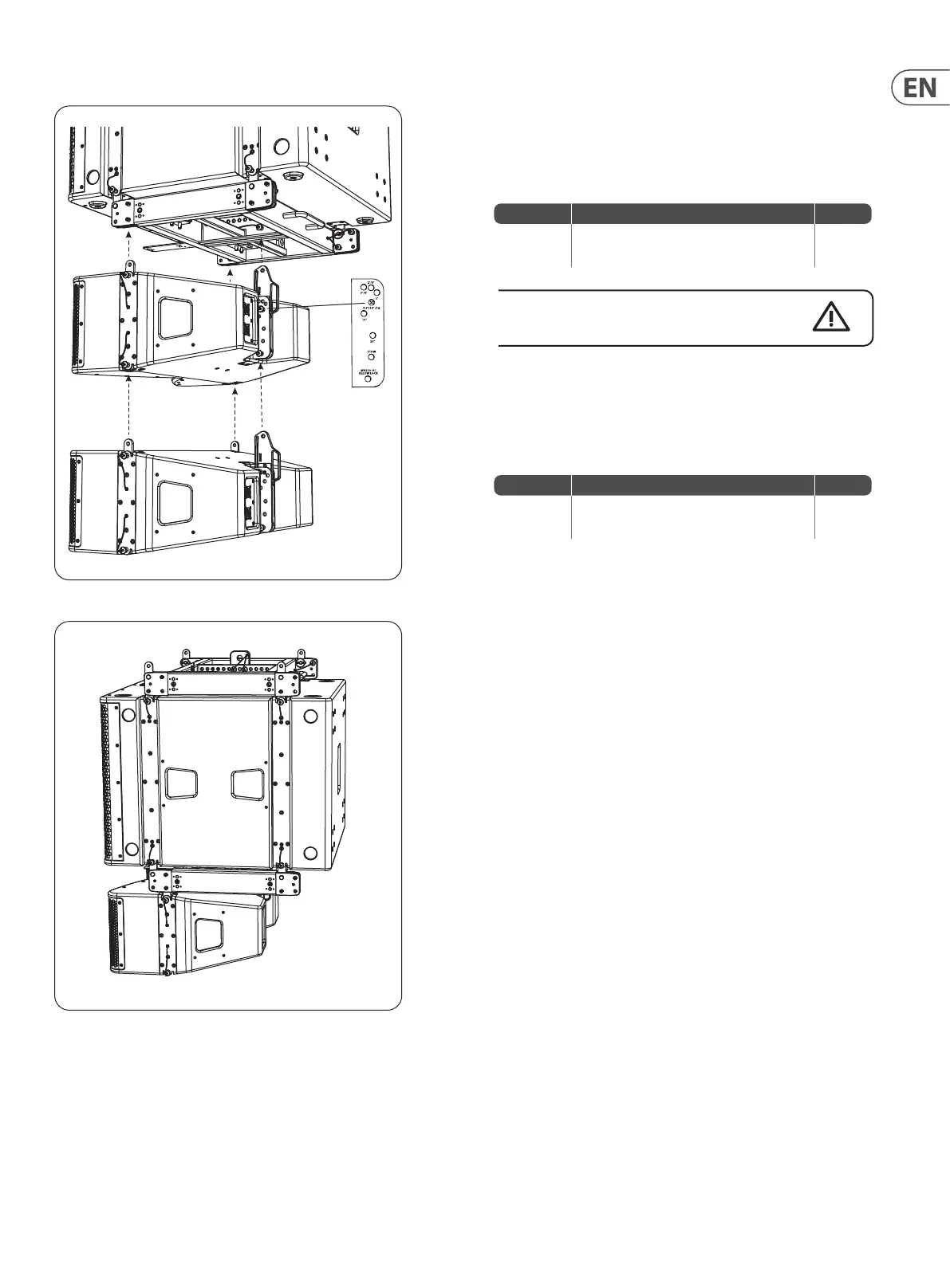
Procedure 5.2 - Attaching the MV210-HC Cabinets to the MS121 Subwoofer
1. Perform the previous procedure in Chapter 3: Procedure 3.1 steps 3 to 12,
to attach MV210-HC cabinets to the lower MAN210-FG y grid.
Note: Set the angle of the rst cabinet to be horizontal, by inserting the rear
rigging pin in the sliding angle plate '7.5/15/FG' hole.
Procedure Description of Work Check
3.1 step 3 to
step 12
Connecting MV210-HC cabinets to the
MAN210-FG y grid
Double check all pins are correctly inserted, and that the MV210-HC
cabinets are securely attached to the MAN210-FG y grid.
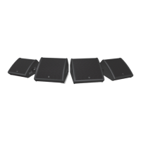
2. Add further MV210-HC cabinets below the rst MV210-HC cabinet, in a
similar way.
3. Alternatively, a previously-assembled group of MV210-HC cabinets can be
assembled to the lower MAN210-FG y grid. See Chapter 3, Procedure 3.2:
Adding a group of MV210-HC Cabinets to the MAN210-FG Fly Grid.
Procedure Description of Work Check
3.2
Adding a group of MV210-HC cabinets to the
MAN210-FG y grid
 Loading...