44 Manchester Series MAN210-FG/MS121/MAN210-HC Rigging Manual
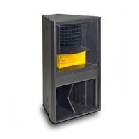
1. Perform the previous procedure in Chapter 6 to join two MS121 subwoofers
as a groundstack.
Procedure Description of Work Check
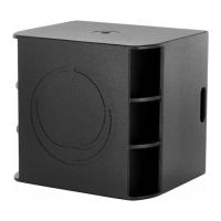
6.1 Assemble two MS121 Subwoofers
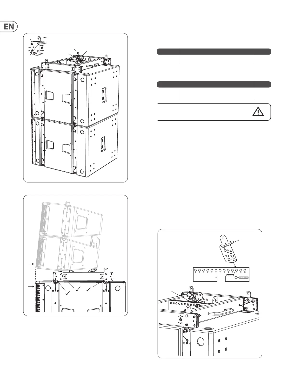
2. Perform the previous procedure in Chapter 5 to attach the MAN210-FG y
grid to the top of an MS121 subwoofer.
Procedure Description of Work Check
5.1 Attaching an MAN210-FG y grid to an MS121
subwoofer
Double check all pins are correctly inserted, and that the
MAN210-FG y grid is securely attached.
3. Make sure that the MAN210-FG y grid is in the position as shown on top
of the subwoofer, using rigging pins in the forward holes of the y grid to
connect to the top links of the subwoofer. This position will move the y grid
rearwards on the subwoofer. (If it is in the forward position, then the front
grilles of the MV210-HC cabinets will be forward of the subwoofer grilles.)
4. Make sure that the front L-shaped Links (1) are as shown, not in the front
position, and that they are secured with the rigging pins (2) and Clevis pins
(3).
5. If the single shackle plate has been used, remove it and attach it to the
stowage postion in the MAN210-FG y grid, using its own rigging pins.
6. Pull out the ground stack plate (4) from the MAN210-FG y grid stowage
location, and attach it to hole 11 of the center spine of the MAN210-FG y
grid, using one of the attached rigging pins (5). Only hole 11 should be used.
The plate holes are marked with the following angles: -6 , -4 , -2, 0, 2, 4, and
6 degrees. Choose the angle that you want to set the rst MV210-HC cabinet
from horizontal.
Procedure 7.1 - Attaching the MAN210-FG y grid to the MS121 Subwoofer stack
1
2
3
1
2
4
5
4
Only use
Hole 11
Front
 Loading...