45 Manchester Series MAN210-FG/MS121/MAN210-HC Rigging Manual
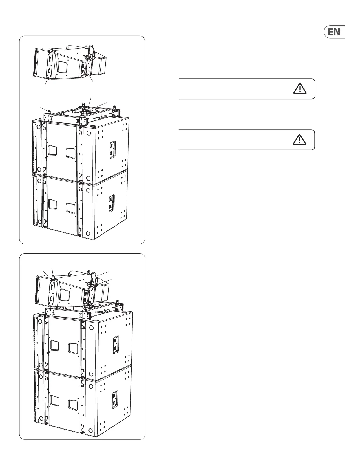
7. Prepare the rst MV210-HC cabinet, by pulling out the front lower rigging
pins (6), and the rear lower rigging pin (7).
8. Carefully lift the MV210-HC cabinet until its lower front mounting slots t
over the 2 front links (1) of the MAN210-FG y grid. Reinsert the front pins
(6) to secure the MAN210-FG y grid links (1) to the MV210-HC.
Take care not to trap your ngers between components.
9. Align the MV210-HC cabinet's rear lower mounting hole with the top hole
(8) in the ground stack plate (4). Reinsert the rear pin (7) to secure the rear of
the MV210-HC to the ground stack plate.
Double check that all pins are correctly inserted,
before proceeding further.
10. Prepare the MV210-HC for the next MV210-HC cabinet, by pulling out the 2
front upper rigging pins (9). The spring-loaded top links (10) will move to the
up position. Reinsert the pins (9) to secure the links in the up position.
11. Pull out the rear upper rigging pin (12), and slide the MV210-HC's rear
mounting plate (11) upwards and reinsert the rigging pin (12) into one of the
available holes. Each hole is marked with an angle; choose the hole which
matches the angle you want to set the next MV210-HC.
6
1
8
4
7
9
10
11
12
 Loading...