16
5.6 COOLING WATER CONNECTIONS
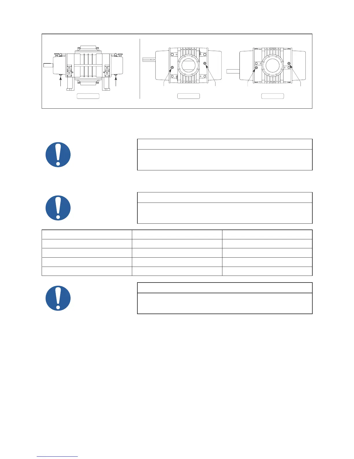
Figure 6 - Water Cooling Connections
SIDE BOTTOMTOP
1/8” NPT
WATER INLET
TYPICAL PORT LOCATIONS ARE SHOWN HERE.
1/2” NPT
WATER OUTLET
1/2” NPT
WATER OUTLET
1/2” NPT
WATER INLET
1/2” NPT
WATER INLET
1/8” NPT
WATER OUTLET
3200/4000/5000 SERIES 7000 SERIES
5.7 COOLING WATER SPECIFICATIONS
NOTE
FLOW RATE: Less than 2 GPM total both end plates.
MAXIMUM PRESSURE: 100 PSIG
5.8 DRIVE COMPONENTS
NOTE
Refer to the following drawings for applicable drive components – motor
adaptor kit and coupling:
SERIES NEMA DRAWING IEC DRAWING
3200 32172 32173
4000 40111 40110
5500 55228 55227
7000 77131 77129
NOTE
Only approved drive system components shall be used to maintain CE
compliance.
5.9 MOTOR DRIVE
5.9.1 DIRECT COUPLED
When installing the motor directly to the booster, align shafts to coupling in accordance with the coupling
manufacturer’s instructions. Boosters shipped with motor directly coupled and mounted on a common base
have been aligned prior to shipment and normally no further alignment is necessary. However, alignment
should be checked and adjustments made if necessary prior to starting the unit.
Coupling halves must correctly t the booster and drive shafts so that only light tapping is required to install
each half. The two shafts must be accurately aligned, A direct coupled booster and motor must be aligned
with the two shafts not having more than .005” (.13 mm) T.I.R. (Total Indicator Reading). Face must be
aligned within .002”(.05 mm) .
 Loading...