33
9.2.4 HOUSING AND FREE END ASSEMBLY
11. Place a small bead of sealer around the
periphery of the end plate, encircling each bolt
hole. Install rotor housing [3] and secure with
four screws evenly spaced.
12. Check clearance between the end of lobes and
the housing using a at bar and feeler gauges
or a depth micrometer. Refer to Assembly
Clearances table for free end clearances.
13. Place a small bead of sealer around the
periphery of the housing, encircling each bolt
hole. Install free end plate and secure with
four screws.
14. 90/91 Series - Install mating rings in the
same way as the gear end, No. 5.
92/93 Series - Install seal slinger in the same way as the gear end. Install bearing spacers [123] on
each shaft.
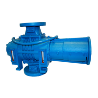
15. Lubricate shafts and install roller bearings [10]
NOTE
Inner race of bearing has a ange on one side only. This ange must face
outward. See Figure 14.
16. Install oil retainer rings and screws [14 & 30], spacer [57] (Model 5500 only), washer [25], screw [29],
oil slinger and dowel [21 & 68], and screw [69].
NOTE
Oil slinger should always be mounted on lower rotor for horizontal ow
units. It can be mounted on either shaft for vertical ow units.
17. Lay booster assembly down and torque timing gear nuts at this time. See Torque table on page 41 for
proper torques.
9.2.5 ADJUSTING ROTOR INTERLOBE CLEARANCE
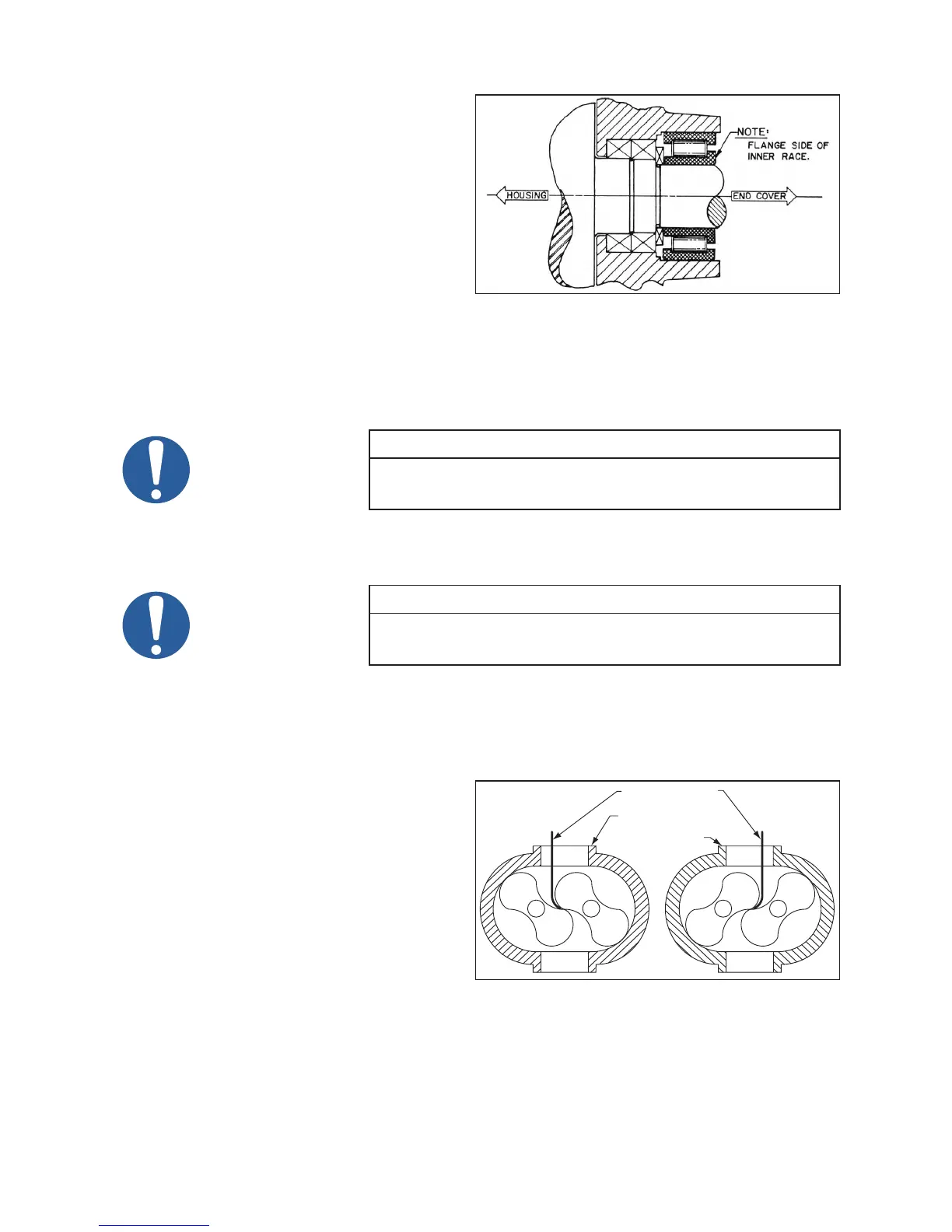
18. Using feeler gauges take interlobe readings
and record on each side of housing as
indicated in Figure 15. By removing or
adding shim behind the helical gear, it rotates
as it is moved in or out and the driven rotor
turns with it, thus changing the clearance
between rotor lobes.
Changing the shim thickness .006” (.15 mm)
will change the rotor lobe clearance .003”
(.08 mm) or one-half the amount.
EXAMPLE: Referring to Figure 15 to the
right, check the clearance a AA (right hand reading) and BB (left hand reading). If AA reading is .009”
(.23 mm) and BB reading .003” (.08 mm) by removing .006” (.15 mm) shims, the readings will change
one-half the amount removed or .003” (.08 mm) AA should then read .006” (.15 mm) and BB should
read .006” (.15 mm). The nal reading should be within .002” (.05 mm) of each other.
To determine the amount of shim to add or remove, subtract the small gure from the larger. If the
Figure 14 - Roller Bearing Flange
A
BB
B
A
B
A
A
A
A
B
A
B
B
A
B
LONG FEELER GAUGE
RECORD A-A
READING HERE
RECORD B-B
READING HERE
Figure 15 - Checking Rotor Interlobe Clearance
 Loading...