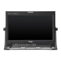
- Provides connection to control equipment for external monitor control.
- Features can be changed in the [REMOTE] section of OSD menu.
DVI DIGITAL/DVI ANALOG (DVI-I)
- Input connection for DVI digital/analog.
- HD/SD-SDI signal input terminal.
- Interlocks with front tally lamp.
- HD/SD-SDI signal output terminal.
- Signal input terminal used to feed the monitor COMPOSITE 1, S-VIDEO Y, COMPONENT Y and RGB
- Signal input terminal used to feed the monitor COMPOSITE 2, RGB B and COMPONENT Pb signals.
- Signal input terminal used to feed the monitor COMPOSITE 3, S-VIDEO C, COMPONENT Pr and
- Internal speakers stereo audio input terminal.
- Built in audio disembedder and internal speakers stereo audio output using mini jacks.
When using the product, make sure to connect the GND rst before connecting the input signal line.
The unit may not operate properly if the
input line is connected before the GND is
Connector Composite Component S
-
Video
1 CVBS 1 Pb B No Con.
2 CVBS 2 Y G Y
3 CVBS 3 Pr R C
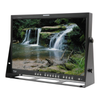
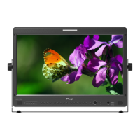
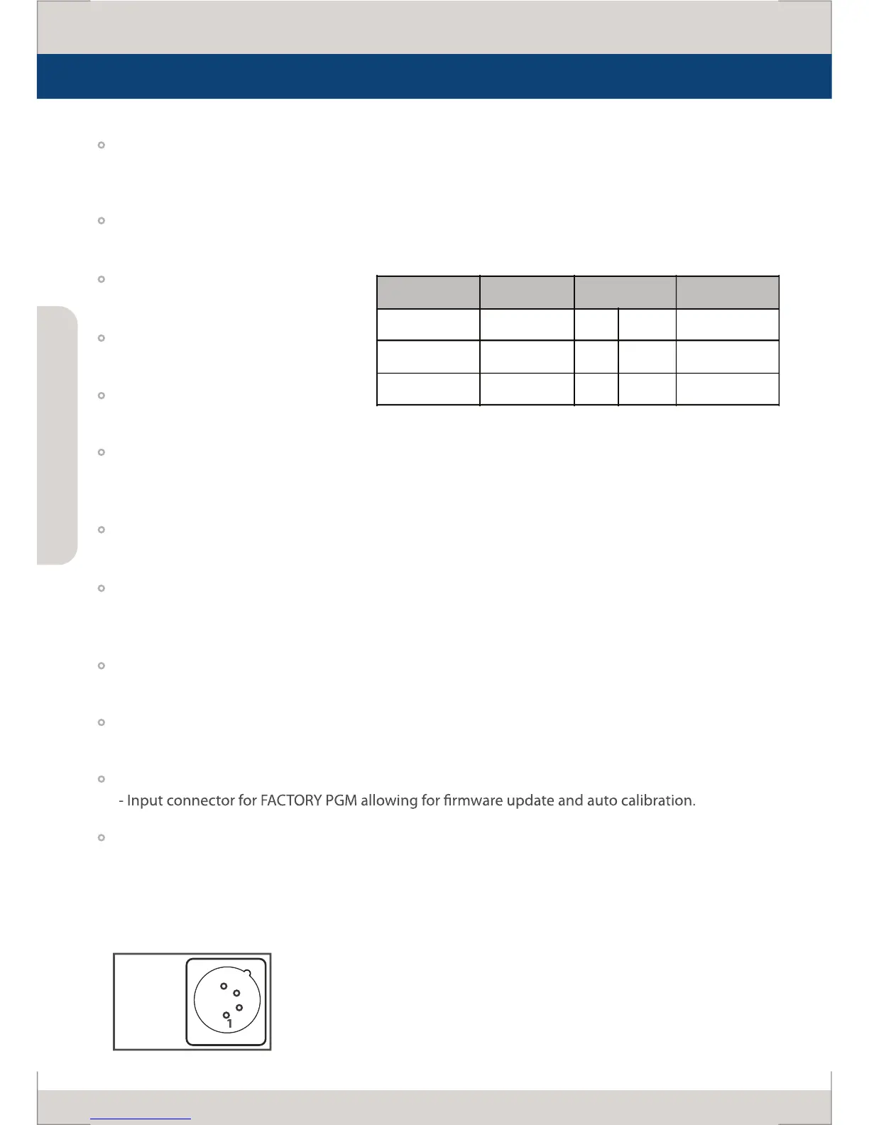
Name & Function of Each Part
 Loading...