Signal
Pin
FG 1
TXD 2
RXD 3
CTS 5
DSR 6
SG 7
DTR 20
(1) Connector pin configuration
Connector used:
TM5RJ3-66 (Hirose) or
equivalent
Applicable connector:
TM3P-66P (Hirose) or
equivalent
(2) Electric characteristics
1) Drive voltage: 24 VDC
2) Drive current: Approx. 1 A max. (not to exceed 510 ms.)
3) DRSW signal: Signal levels: “ L” = 0 to 0.8 V, “ H” = 2 to 3.3 V
(3) DRSW signal
DRSW signal status can be tested with the DLE+EOT, GS+a, or GS+r
command or at pin 34 on the parallel interface port.
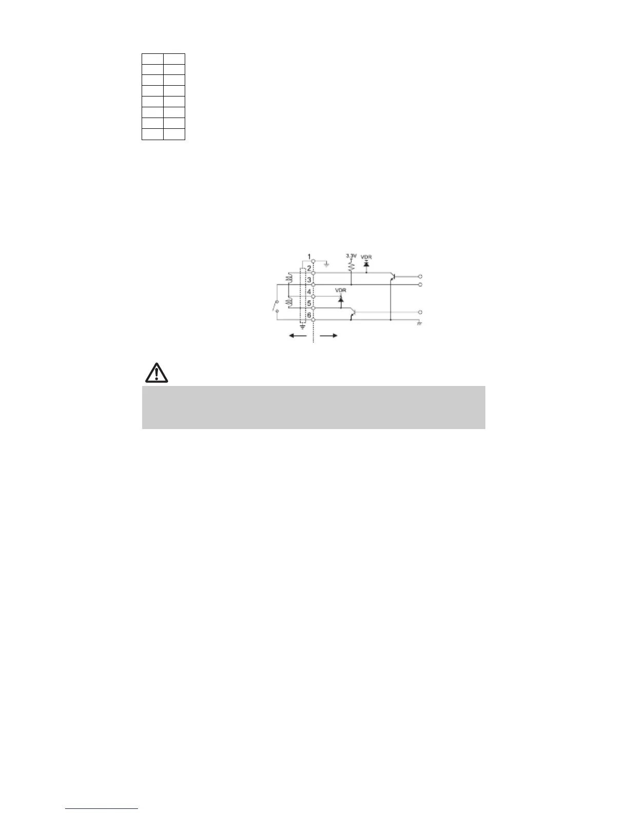
(4) Drive circuit
Cash drawer kick-out connector
Shielded
Cash drawer open/
close switch
Cash drawer
Printer
CAUTION
Cash drawers 1 and 2 cannot be operated at the same time.
The solenoid used for the cash drawer should be 24 ∧ or more. Do not allow the
electric current to exceed 1 A. Excessive current could damage or burn out the
circuits.
— 19 —