http://www.tyan.com
23
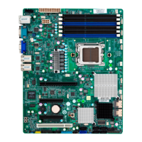
LED28: Standby power LED
Pin Signal
+ P3V3_AUX
- GND
State Color Description
On Green Standby Power OK
Off Off No power
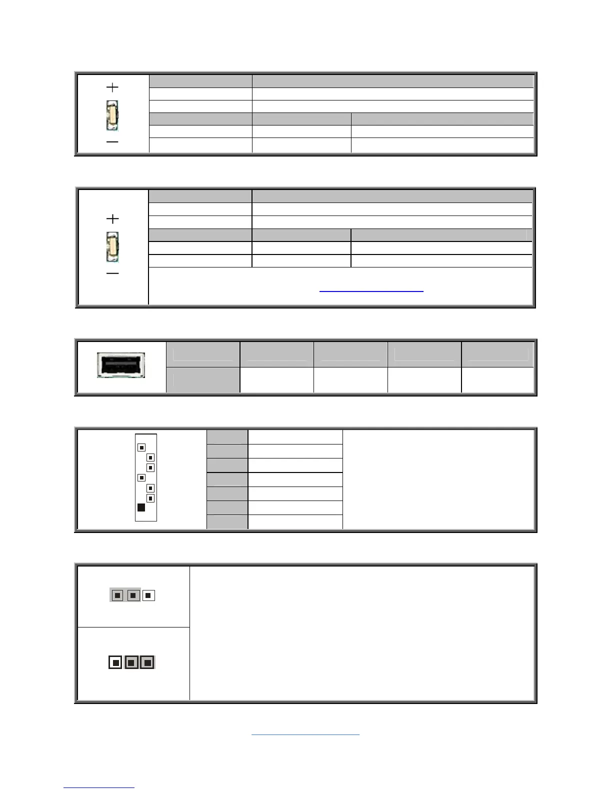
LED29: ID LED
Pin Signal
+ P3V3_AUX
- ID_SW_L
State Color Description
On Blue System identified
Off Off System not identified
NOTE: IPMI can activate ID LED from remote site.
Please visit the TYAN Web Site at http://www.tyan.com
to download the
latest AST2050 Software Configuration Guide for IPMI settings.
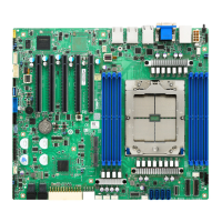
USB3: Vertical (Type A) USB Connectors
Pin 1 2 3 4
Signal +5V USB D- USB D+ GND
J43/J44/J45/J46/J47/J48: Serial ATA Connector
7 GND
6 RXP
5 RXN
4 GND
3 TXN
2 TXP
7
1
1 GND
Connects to the Serial ATA ready
drives via the Serial ATA cable.
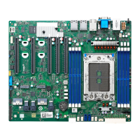
J72: Clear CMOS Jumper
Clear CMOS
You can reset CMOS by using this jumper if you have
forgotten your system/setup password or need to clear BIOS
setting.
1. Power off system and disconnect both power connectors
from the motherboard.
2. Use jumper cap to close Pin_2 and Pin_3 for seconds to
Clear CMOS.
3. Put jumper cap back to Pin_1 and Pin_2 (default setting).
4. Reconnect power & power on system.