TFP1321
Page 15 of 18
Step 6. Reset the electric detection
system in accordance with the manu-
facturer’s instructions to de-energize
the Solenoid Valve (S), and proceed as
follows:
• Water should cease draining from the
Solenoid Valve (S) but remain drain-
ing from the Manual Reset Actuator
(N).
• Press the Reset Knob on the Man-
ual Reset Actuator (N) and hold it a
few seconds until water stops flow-
ing from its drain tube.
• Pressure will then build up in the
DV-5
a Diaphragm Chamber.
• After system pressure is restored
in the DV-5
a Diaphragm Chamber,
inspect the Solenoid Valve (S) and
Manual Reset Actuator (N) for leaks
at the drain tube. Any leaks must be
corrected before proceeding to the
next step.
Step 7. Partially open the System Main
Control Valve (B). Slowly close the Main
Drain Valve (D) as soon as water dis-
charges from the Main Drain Valve (D).
Observe the Automatic Drain Valve
(F) for leaks. If there are leaks, deter-
mine/correct the cause of the leakage
problem. If there are no leaks, the
DV-5
a Valve is ready to be placed in
service and the System Main Control
Valve (B) must then be fully opened.
Internal Valve Inspection
Once every five years during the
annual operational test procedure,
and prior to the DV-5
a Valve being
reset and the DV-5
a Valve de-pres-
surized, the interior of the DV-5
a Valve
must be cleaned and inspected for
wear and damage. Damaged or worn
parts must be replaced. Replacement
of the Diaphragm every ten years is
recommended, or more frequently if
inspections and/or wear and tear of
the Diaphragm warrants more frequent
replacement.
NOTICE
The Diaphragm Cover may be removed
between Steps 4 and 5 of the Valve
Setting Procedure instructions, since
at that point the DV-5
a Valve should
be de-pressurized as evident by a
zero gauge reading on the Diaphragm
Gauge (K) and Water Supply Gauge (J),
as well as no water discharging from
the Automatic Drain Valve (F).
To perform internal valve inspection
between Steps 4 and 5 of the Valve
Setting Procedure, remove the Dia-
phragm cover as follows:
Step 1. Close the Inverted Flare Shut-
Off Valve (R).
Step 2. Remove the Copper Tube
Fitting between the Diaphragm Supply
Valve (P) and the Inverted Flare Shut-
Off Valve (R).
Step 3. Loosen the union securing the
Electric Actuation Trim and remove the
Actuation Trim.
Step 4. Loosen and remove the union
between the Diaphragm Cover and the
MRA-1 Manual Reset Actuator (N) and
remove the MRA-1 Manual Reset Actu-
ator (N) subassembly.
Step 5. Remove the Diaphragm Valve
Cover hardware, then slowly remove
the Diaphragm Cover and perform
internal valve inspection. Clean the
valve interior and replace parts as
necessary.
After cleaning and inspecting valve
interior, and replacing parts as nec-
essary, reinstall the Diaphragm Cover
by completing the following steps to
assure the Diaphragm Cover Fasteners
are uniformly and securely tightened.
Step 1. With reference to Figure 1,
ensure that the Diaphragm is properly
oriented and that the proper hardware
arrangement is utilized when assem-
bling the Diaphragm Covers. The hard-
ware arrangements differ depending on
the size of the DV-5
a Valve.
Step 2. By first using the Long Hex
Bolts, support of the Diaphragm Cover
will be provided before installing the
Short Hex Bolts. Align Diaphragm in
proper orientation with Valve Body, and
then align Diaphragm Cover in proper
orientation with Valve Body. Hand-
tighten all fasteners.
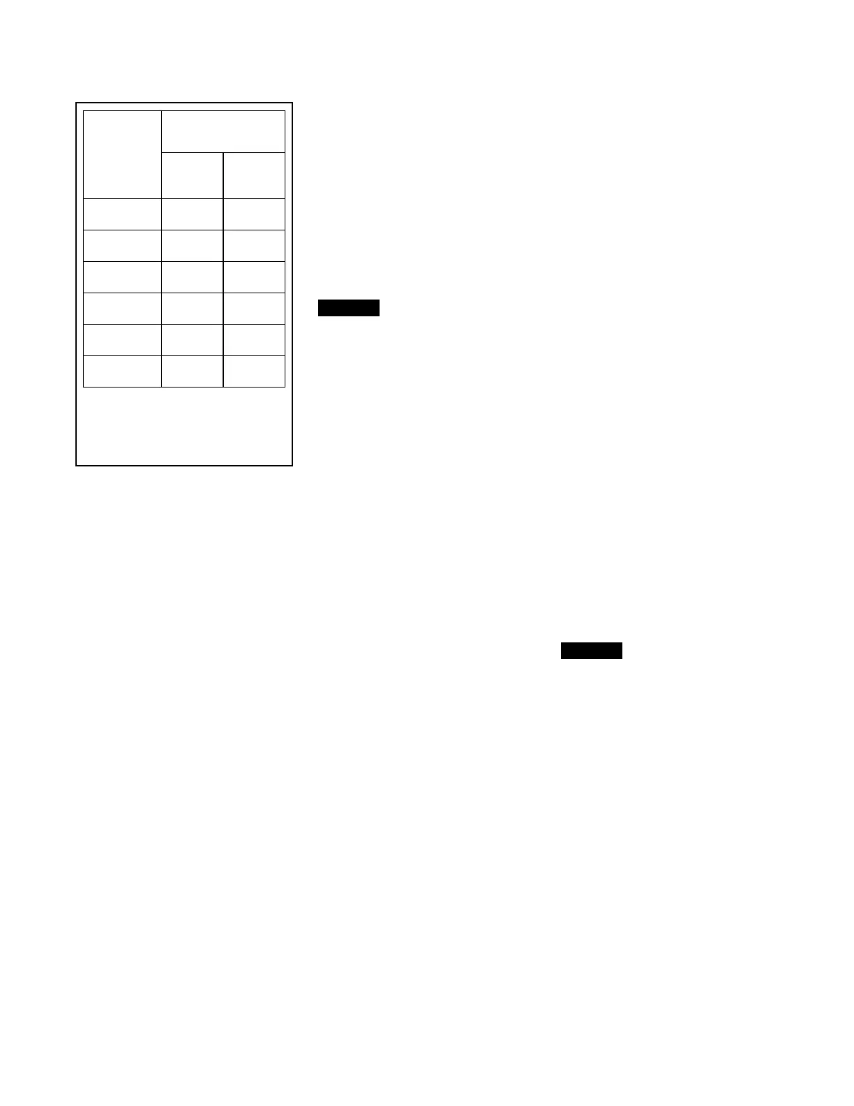
Step 3. Using crossdraw sequence
to assure uniformity, wrench-tighten
Long Hex Bolts and Short Hex Bolts
to appropriate torque values. Repeat
crossdraw sequence two to three
times at incremental torque valves
until reaching the torque valves found
in Table C.
Step 4. Inspect to assure all Hex Bolts
are securely tightened.
Step 5. Using the union, secure the
MRA-1 Manual Reset Actuator to the
Diaphragm Cover.
Step 6. Using the union, secure the
Electric Actuation Trim.
Step 7. Replace the Copper Tube
Fitting between the Diaphragm Supply
Valve (P) and the Inverted Flare Shut-
Off Valve (R).
Step 8. Ensure that the unions and flare
fittings are securely tightened.
Step 9. With the Diaphragm Supply
Valve (P) closed, fully open the Inverted
Flare Shut-Off Valve (R) stainless steel
screw (approximately 1/2 in.) until resis-
tance is met so as not to break the
internal roll-pin. The internal roll-pin
stops the removal of the Inverted Flare
Shut-Off Valve (R) stainless steel screw.
Step 10. Proceed with Step 5 of the
Valve Setting Procedures section in this
data sheet.
NOTICE
If the water supply contains chemicals
which tend to attack a polyester fabric-
reinforced, EPDM rubber or the five
year inspection indicates a build-up of
debris within the DV-5
a Valve that could
affect its proper operation, then the
frequency of the internal valve inspec-
tion procedure must be appropriately
increased.
With reference to Figure 1, make
certain that the Diaphragm is correctly
oriented; otherwise, the DV-5a Deluge
Valve cannot be properly set.
Under-tightening the Diaphragm Cover
Bolts can result in internal and external
leakage.
Use only TYCO replacement fasteners
as specified in Figure 1.
Do not apply adhesives, lubricants, or
other substances to the Diaphragm or
Valve Body.
Nominal
Valve Sizes
ANSI
Inches
(DN)
Torque
lb-ft
(N∙m)
Nuts
Short
Hex
Bolts
1-1/2
(40)
44
(59,7)
35
(47,5)
2
(50)
44
(59,7)
35
(47,5)
3
(80)
188
(254,9)
150
(203,4)
4
(100)
396
(536,9)
316
(428,4)
6
1
(150)
265
(359,3)
212
(287,4)
8
(200)
545
(738,9)
436
(591,1)
NOTES
1. Also applicable to metric 165,1 mm size.
TABLE C
DIAPHRAGM COVER BOLTS
MINIMUM TORQUE
 Loading...


