TFP1321
Page 9 of 18
NOTES
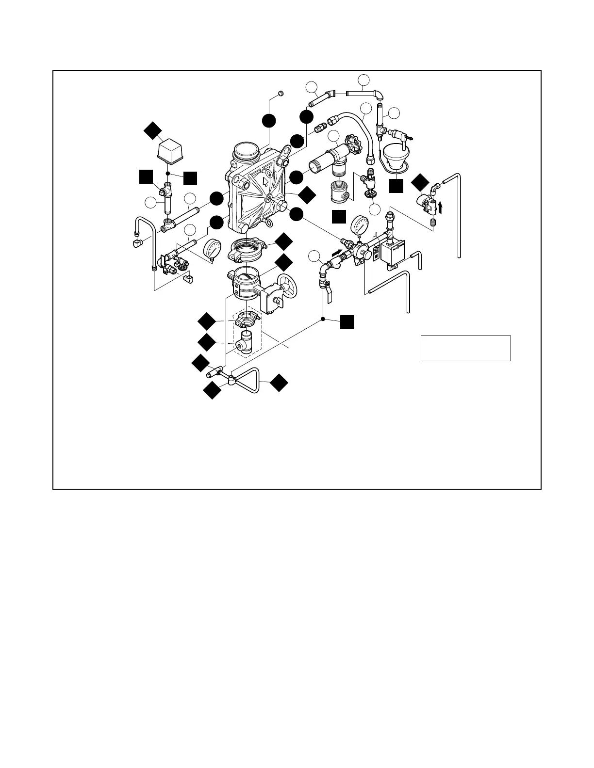
1. Port Connections P1 through P7 are described in Figure 2.
2. External Trim Connections C1 through C5 are described in Figure 18.
3. When ordering pre-assembled "DV-5
A Valve with Galvanized Trim" or pre-assembled "DV-5A Valve with Galvanized Trim and Buttery Valve", Items A1 through A9 are provided,
as applicably related to valve size, and Item A9 is provided as P/N 52-287-1-124 described in Technical Data Sheet TFP2180.
4. When ordering DV-5
A Trim separately from the DV-5A Valve, Items A1 through A9 are separately ordered. Water Pressure Gauges for EMEA valve trim are also separately ordered.
Assemble in order
from A to K
C4
C5
C3
C2
C1
P1
P2
P3
P6
P7
P4
P5
1-1/2" (DN40) AND 2" (DN50)
VALVES ONLY
A6
A1
A4
A3
A4
A5
A2
A7
A9
A8
E
D
C
A
B
G
H
F
J
K
FIGURE 5
DV-5
A VALVE
DELUGE ELECTRIC ACTUATION TRIM
SEMI-ASSEMBLED
 Loading...


