NO.
(a)
DESCRIPTION P/N
REPLACEMENT PARTS
Diaphragm Kit, Includes Item 2
92-477-1-105DN40 Valve
92-477-1-107DN50 Valve
92-477-1-109DN80 Valve
92-477-1-101DN100 Valve
DN150 Valve 92-477-1-103
DN200 Valve 92-477-1-111
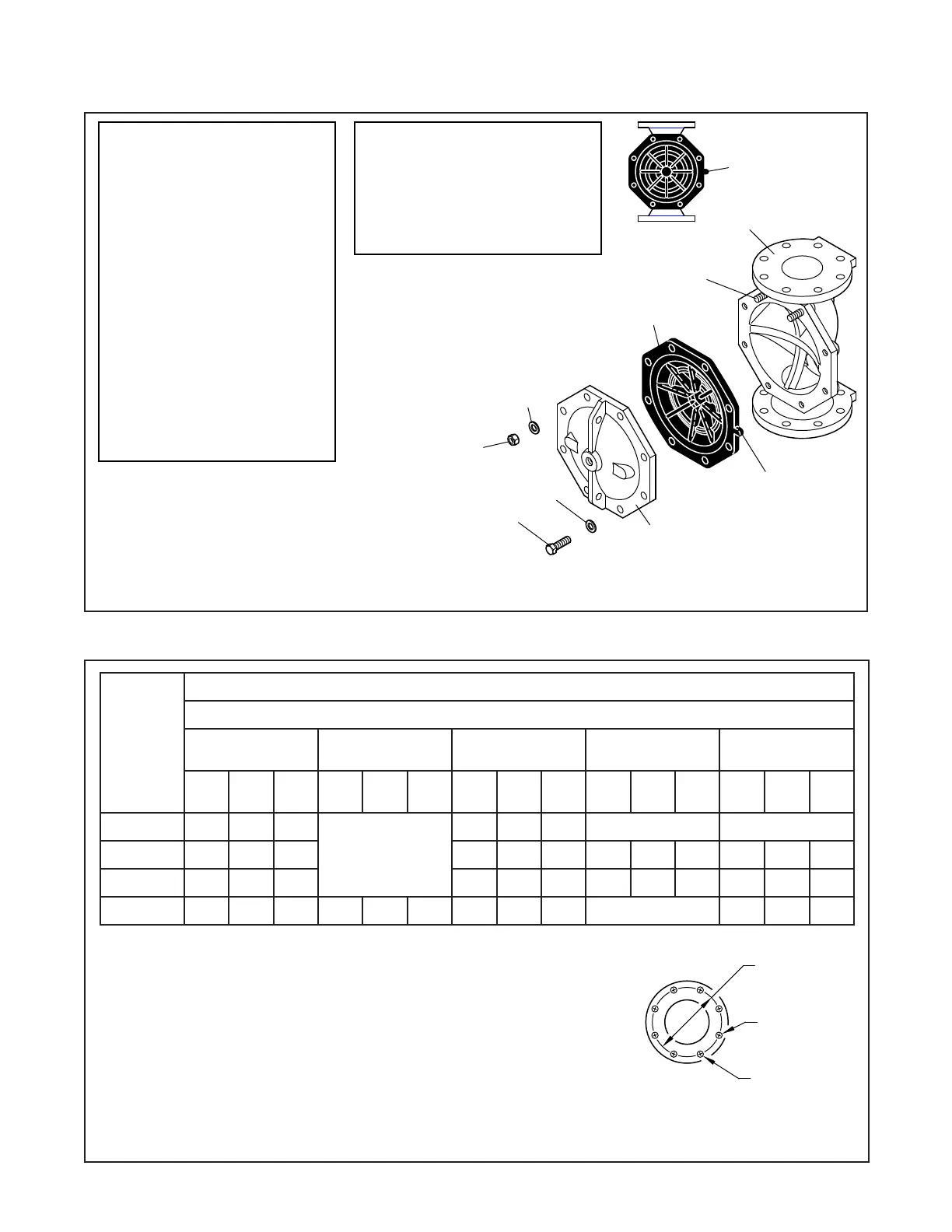
DIAPHRAGM
ORIENTATION
TAB
TAB ORIENTED
PERPENDICULAR
TO VALVE BODY
DIAPHRAGM
3
6
(DN100, DN150,
& DN200 VALVES
ONLY)
5
4
STUDS,
SEE NOTE 2
2
1
4
1.
NOTES:
NR - Not Replaceable.
2. DN100, DN150, & DN200 Valve Bodies
are equipped with studs as shown,
allowing Diaphragm and Handhole
Cover to be "hung" in place to
ease assembly. Bodies of DN40, DN50,
& DN80 Valves are not equipped with
studs.
. . . . . . . . . . . . . .
. . . . . . . . . . . . . .
. . . . . . . . . . . . . .
. . . . . . . . . . . . .
. . . . . . . . . . . . .
. . . . . . . . . . . . .
Hex Bolt,
DN100 Valve,
DN150 Valve,
5
M16 x 50 CH
DN50 & DN80 Valves,
CHDN40 Valve, M12 x 30
Hex Nut,6
DN200 Valve,
DN100 & DN150 Valves,
CHDN200 Valves, M20
Handhole Cover NR
4 Flat Washer,
NO.
1
QTY.DESCRIPTION Refer to Kit
(a)
Valve Body
Diaphragm
NR
2
3
VALVE PARTS
DN40 Valve, M12 CH
CH
DN50 & DN80 Valves,
DN100 & DN150 Valves,
CHDN200 Valves, M20
M16
CHM16
M16 x 50 CH
M16 x 55 CH
M20 x 70 CH
CHM16
4
4
2
1
1
1
4
4
8
8
6
6
6
2
. . . . . . . . . . . . .
. .
. . . .
. . . . . . .
. . . . . . . . . . .
. . . . . . . . . . .
. . . . . .
. . . . . . . . . . . . . . . . .
. . . .
. . . . . . . . . . . . . . . . .
. . . . . . . . . . . . .
. . . . . . . . . . . . .
. . . . . . . . . . . . .
. . . . . . . . . . . . . . . . .
Same drilling as for BS 4504 Section 3.2 (PN16) and DIN 2532 (PN16).
Same drilling as for BS 4504 Section 3.2 (PN10) and DIN 2532 (PN10).
Dim. A
Bolt Circle
Diameter
Dim. B
Bolt Hole
Diameter
Qty. N
Number of
Bolt Holes
3
4
Flange end DN40 & DN50 DV-5 Valves are not offered.
1
Same drilling as for B16.5 (Class 150) and B16.42 (Class 250).
2
FIGURE 1
DN40 thru DN200 MODEL DV-5 DELUGE VALVE
— ASSEMBLY —
TABLE A — DIMENSIONAL SPECIFICATIONS FOR SELECTION OF FLANGE DRILLING
Nominal
Valve
Size
1
Flange Drilling Specification
Nominal Dimensions in Millimeters
ANSI B16.1
(Class 125)
2
ISO 7005-2
(PN10)
3
ISO 7005-2
(PN16)
4
JIS B 2210
(10K)
AS 2129
(Table E)
Dim.
A
Dim.
B
Qty.
N
Dim.
A
Dim.
B
Qty.
N
Dim.
A
Dim.
B
Qty.
N
Dim.
A
Dim.
B
Qty.
N
Dim.
A
Dim.
B
Qty.
N
DN80 152,4 19,0 4
USE
ISO 2084
(PN16)
160,0 19,0 8 N/A N/A
DN100 190,5 19,0 8 180,0 19,0 8 175,0 15,0 8 178,0 18,0 8
DN150 241,3 22,2 8 240,0 23,0 8 240,0 19,0 8 235,0 22,0 8
DN200 298,5 22,2 8 295,0 23,0 8 295,0 23,0 12 N/A 292,0 22,0 8
Page 2 of 28 TFP1338