Technical
Data
Approvals:
VdS and LPCB Approved when
trimmed as detailed in this Technical
Data Sheet for
European Conformity
applications.
Deluge Valve:
Components for the DN40 thru DN200,
Model DV-5 Deluge Valves are shown
in Figure 1. The DV-5 Valves are for
vertical installations. They are rated
for use at a service pressures of 1,4
to 16,0 bar, except that the DN50 has
a minimum operating pressure of 2,0
bar, and the minimum residual pres-
sure for sizes DN40 thru DN200 must
be 2,0 bar for flow velocities greater
than 8,5 m/s.
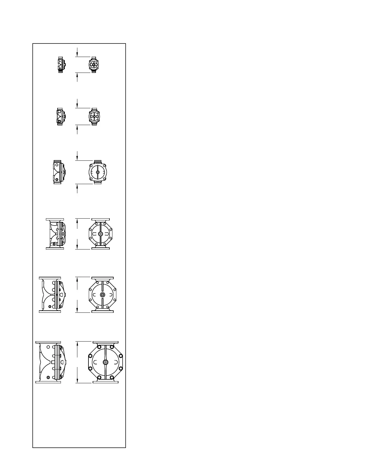
The take-out dimensions are shown in
Figure 2, and the flanged connections
are available drilled per ANSI, ISO, AS,
and JIS specifications (Ref. Table A).
The DV-5 Valves are provided with
ISO 7/1 threaded ports that will readily
accept the trim arrangements detailed
in this Technical Data Sheet.
Pressure Loss:
Refer to Graph A on Page 5.
Patents:
U.S.A. : 6,095,484
Materials Of
Construction
Body. Rilsan* coated ductile iron per
ASTM A536-77, Grade 65-45-12.
Handhole Cover. Rilsan* coated duc-
tile iron per ASTM A536-77, Grade
65-45-12.
Diaphragm. Nylon fabric reinforced,
natural rubber per ASTM D2000.
Diaphragm Cover Fasteners. Galva-
nized carbon steel.
*Rilsan is a registered trademark of
ATOFINA Chemicals, Inc. (The Rilsan
coating is a polyamide (Nylon 11)
coating.)
Operating
Principles
The Model DV-5 Deluge Valve is a
diaphragm style valve that depends
upon water pressure in the Diaphragm
Chamber (Ref. Figure 3A) to hold the
Diaphragm closed against the water
supply pressure. When the DV-5 Valve
is set for service, the Diaphragm
Chamber is pressurized through the
trim connections from the inlet side of
the system’s stop valve. Opening an
actuation device, for example the so-
lenoid valve in the Electric Actuation
Trim (Ref. Figure 6), releases water
from the Diaphragm Chamber faster
than it can be replenished through the
3,2 mm restriction within the Automat-
ic Shut-Off Valve provided in the dia-
phragm chamber supply connection.
Release of water pressure results in a
rapid pressure drop in the Diaphragm
Chamber and the force differential ap-
plied through the Diaphragm to hold
the Diaphragm in the set position is
reduced below the valve trip point.
The water supply pressure then forces
the Diaphragm open permitting water
to flow into the system piping, as well
as through the Alarm Port to actuate
the system alarms (Ref. Figure 3B).
Groove x Groove & Thread x Thread
Groove x Groove & Thread x Thread
Groove x Groove, Flange x Flange,
& Flange x Groove
Groove x Groove, Flange x Flange,
& Flange x Groove
Groove x Groove, Flange x Flange,
& Flange x Groove
460 mm
400 mm
324 mm
220 mm
204 mm
570 mm
Groove x Groove, Flange x Flange,
& Flange x Groove
DN40
DN50
DN80
DN100
DN150
DN200
FIGURE 2
MODEL DV-5 DELUGE VALVE
— TAKE-OUT DIMENSIONS —
(Applies to all available
end configurations)
TFP1338 Page 3 of 28