TFP1450
Page 23 of 28
• That the Low Air Pressure Alarm
Switch (U) and Zone 2 of the Releas-
ing Panel, as well as its associated
alarms, operate properly. The Low
Air Pressure Alarm Switch (U) should
operate at the previously established
pressure (refer to Installation section,
Step 9).
• That there is no leakage from the
Solenoid Valve (V).
Step 5. Close the Inspector’s Test
Connection.
NOTE: During this procedure, the Sole-
noid Valve (V) should remain closed and
the DV-5a Valve Diaphragm Chamber
should remain pressurized.
This procedure is used to verify that the
DV-5a Valve will remain set if the Low
Air Pressure Alarm Switch (U) (Zone 2)
operates due to loss of system air pres-
sure and the electric detection system
(Zone 1) remains in a normal condition.
Step 6. Restore the electric fire detec-
tion system to a normal condition in
accordance with the manufacturer’s
instructions after the system air pres-
sure has automatically been restored
to normal.
Step 7. Close the System Shut-Off
Valve (W) after the system air pressure
has been restored to normal.
Step 8. Open the System Main Control
Valve (B) one turn beyond the position
at which water just begins to flow from
the Main Drain Valve (D).
Step 9. Close the Main Drain Valve (D).
Step 10. Close the Air Supply Valve (S).
Step 11. Manually operate Zone 1 of
the Releasing Panel, and then operate
Zone 2 of the Releasing Panel by par-
tially opening the System Drain Valve
(E) to relieve air pressure at the Low Air
Pressure Alarm Switch (U), and verify
the following:
• That the DV-5a Valve operates as is
indicated by a discharge of water
from the System Drain Valve (E) and
the Automatic Drain Valve (F). The
Automatic Drain Valve (F) may or may
not close depending on the flow past
the partially open System Main Con-
trol Valve (B)
• That the Model MRA-1 Manual Reset
Actuator (N) has operated as is indi-
cated by water discharging into the
Drip Funnel from the ½ inch drain
tube connected to the Model MRA-1
Manual Reset Actuator (N)
• That the Waterflow Pressure Switch
(C) and its associated alarms prop-
erly operate
• That the Water Motor Alarm, if appli-
cable, properly operates
NOTE: This procedure simulates auto-
matic system operation upon both
electric detection and loss of system
air pressure.
Electric/Pneumatic Actuation
System Operation Procedure
Proper operation of the DV-5a Valve for
both opening of the DV-5a Valve in a
fire condition, or not opening the DV-5a
Valve in a non-fire condition, must be
verified as follows:
Step 1. Close the System Main Control
Valve (B) and then open the Main Drain
Valve (D).
Step 2. Manually operate the Releasing
Panel and verify the following:
• The operation of the Releasing Panel
and its associated alarms
• That there is no leakage from the Dry
Pilot Actuator (W)
NOTICE
During this procedure, the Solenoid
Valve (V) is opened; however, the
Dry Pilot Actuator (W) should remain
closed and the DV-5a Valve Diaphragm
Chamber should remain pressurized.
This procedure is used to verify that the
DV-5a Valve will remain set if the elec-
tric detection system operates but the
sprinkler system remains in its normally
pressurized condition.
Step 3. Open the Inspector’s Test
Connection but be prepared to close
it immediately after verifying that the
Low Air Pressure Alarm Switch (U) and
its associated alarms operate properly.
The Low Air Pressure Alarm Switch (U)
should operate at the previously estab-
lished pressure (refer to Installation
section, Step 9).
Step 4. Close the Inspector’s Test
Connection.
Step 5. Close the System Shut-Off
Valve (W) after the system air pressure
has been restored to normal.
Step 6. Manually restore the electric
fire detection system to a normal con-
dition in accordance with the manu-
facturer’s instructions. The Solenoid
Valve (V) will then be de-energized and
returned to its normally closed position.
Step 7. Open the System Main Control
Valve (B) one turn beyond the position
at which water just begins to flow from
the Main Drain Valve (D).
Step 8. Close the Main Drain Valve (D).
Step 9. Close the Air Supply Valve (S).
Step 10. Open the Dry Pilot Actuator
(W) by partially opening the System
Drain Valve (E) to relieve air pressure at
the inlet to the Dry Pilot Actuator (W).
Verify that there is no leakage from the
Dry Pilot Actuator (W).
NOTICE
During this procedure, the Dry Pilot
Actuator (W) is opened; however,
the Solenoid Valve (V) should remain
closed and the DV-5a Valve Diaphragm
Chamber should remain pressurized.
This procedure is used to verify that the
DV-5a Valve will remain set if the Dry
Pilot Actuator (W) operates due to loss
of system air pressure and the electric
detection system remains in a normal
condition.
Step 11. Open (energize) the Solenoid
Valve by operating the Releasing Panel
and verify the following:
• That the DV-5a Valve operates as is
indicated by a discharge of water
from the System Drain Valve (E) and
the Automatic Drain Valve (F). The
Automatic Drain Valve (F) may or may
not close depending on the flow past
the partially open System Main Con-
trol Valve (B)
• That the Model MRA-1 Manual Reset
Actuator (N) has operated as is indi-
cated by water discharging into the
Drip Funnel from the ½ inch drain
tube connected to the Model MRA-1
Manual Reset Actuator (N)
• That the Waterflow Pressure Switch
(C) and its associated alarms prop-
erly operate
• That the Water Motor Alarm, if appli-
cable, properly operates
NOTICE
This procedure simulates opening of
both the Dry Pilot Actuator (W) (loss
of system air pressure) and Solenoid
Valve (V) (operation of the Valve Releas-
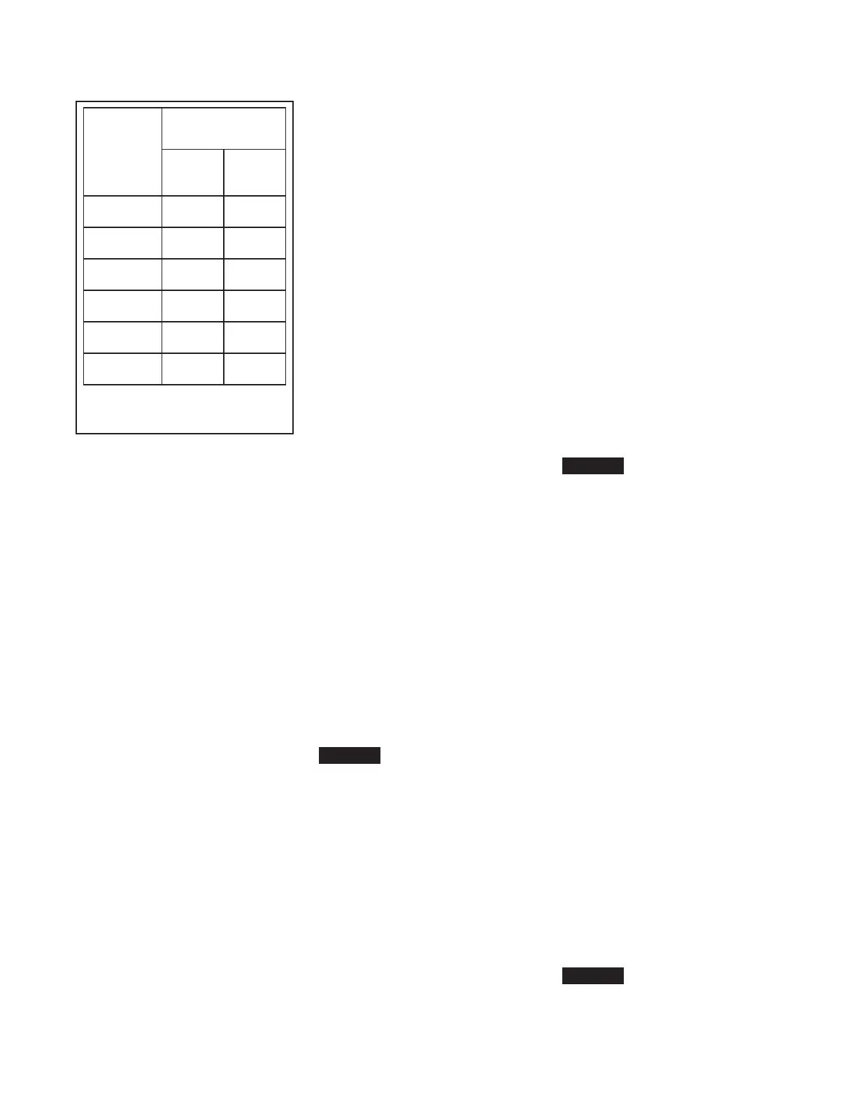
Nominal
Valve Sizes
ANSI
Inches
(DN)
Torque
lb-ft
(N∙m)
Nuts
Short
Hex
Bolts
1-1/2
(40)
44
(59,7)
35
(47, 5)
2
(50)
44
(59,7)
35
(47, 5)
3
(80)
188
(254,9)
150
(203,4)
4
(100)
396
(536,9)
316
(428,4)
6
(150)
265
(359,3)
212
(287,4)
8
(200)
545
(738,9)
436
(591,1)
TABLE B
DIAPHRAGM COVER BOLTS
MINIMUM TORQUE
 Loading...


