tained in compliance with this docu-
ment,aswellaswiththeapplicable
standardsoftheNationalFireProtec-
tion Association, in addition to the
standards of any other authorities
having jurisdiction. Failure to do so
may impair the integrity of these de-
vices.
The F690 Concealed Pendent Sprin-
klers mustnot be usedin applications
where the air pressure above the ceil-
ing is greater than that below. Down-
drafts through the Mounting Cup
could delay sprinkler operation in a
fire situation.
The owner is responsible for main-
taining their fire protection system
and devices in proper operating con-
dition. The installing contractor or
manufacturer should be contacted
relative to any questions.
TECHNICAL DATA
The 1/2 inch (15 mm) orifice Model
F690 Concealed Pendent Sprinklers
are rated for use at a maximum service
pressure of 175 psi (12,1 bar). The
available temperature ratings and
nominal installation dimensions are
given in Figure A. Table 1 summarizes
the maximum permissible ceiling tem-
peratures for use with the F690.
Standard finishes for the Cover Plate
are satin chrome and painted white;
however, other factory painted finishes
for the Cover Plate are available on
special order.
The nominal discharge curves plotted
in Figure C represents the flow “Q” in
GPM (LPM) as determined by the for-
mula:
where the nominal sprinkler discharge
coefficient “K” = 5.6 (80,7); and “p” =
the residual flowing pressure in psi
(bar). Listing standards permit the ac-
tual value of “K” to vary from 5.3 to 5.8
(76,4 to 83,6); however for hydraulic
calculations, a K-factor of 5.6 (80,7) is
to be applied.
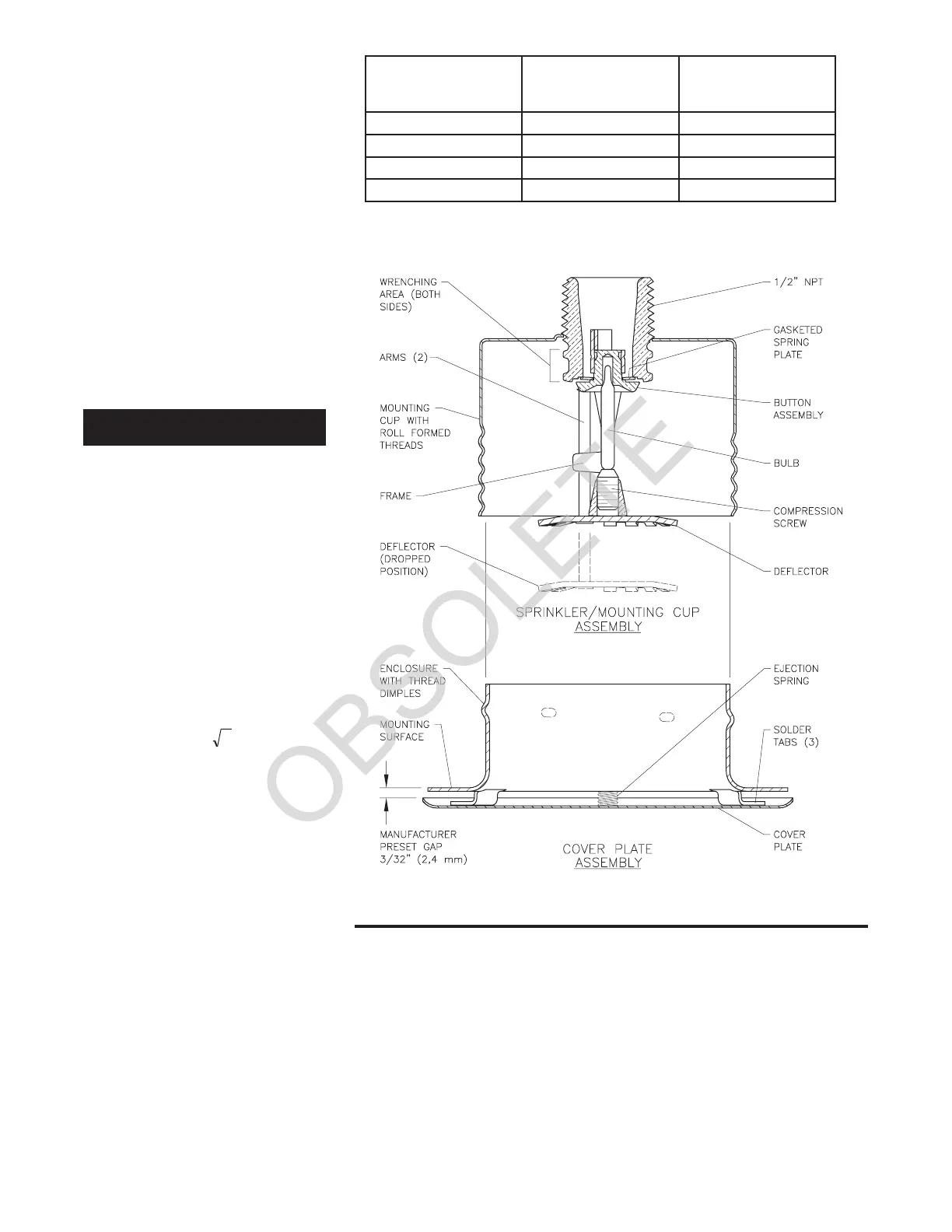
The F690 Sprinkler consists of two
sub-assemblies, as shown in Figure B:
the Sprinkler/Mounting Cup Assembly
and the Cover Plate Assembly.
Sprinkler/Mounting Cup Assembly
The Sprinkler Assembly utilizes a 3
mm Bulb and has a die-cast dezincifi-
cation resistant (DZR) bronze alloy
Frame. The two pieces of the Button
Assembly are constructed from brass
per ASTM B16 (C36000) and copper
(C12200). The Gasketed Spring Plate
consists of an Beryllium Nickel
(N03360) disc spring that is sealed on
both its inside and outside edges with
aTeflon† gasket. The Compression
Screw is brass per ASTM B16
(C36000). The Deflector is bronze per
ASTM B36 (C22000), the Arms are
phosphor bronze per CDA Alloy 510.
The Mounting Cup is chrome plated
low carbon sheet steel.
The Mounting Cup Assembly is pro-
vided with a Protective Cap (Ref. Fig-
ure E), which helps prevent damage to
the Deflector and Arms before the
Cover Plate Assembly is installed.The
Protective Cap is designed such that
the Cap can be opened to expose the
sprinkler for temporary fire protection,
until the ceiling installation is com-
pleted and the Cover Plate can be in-
stalled. The Protective Cap is dis-
carded once the Cover Plate Assembly
is installed.
Cover Plate Assembly
The Cover Plate Assembly, which
screws onto the Sprinkler/Mounting
Cup Assembly, consists of a Cover
Plate which is soldered to an Enclo-
sure at three equidistant locations
around their peripheries. The Cover
Plate and Enclosure are brass per
ASTM B36 (C26000 or C26800). A
Type 302 stainless steel compression
Spring is located between the flange of
QKp
=
SPRINKLER
TEMPERATURE
RATING
COVER PLATE
TEMPERATURE
RATING
MAXIMUM
CEILING
TEMPERATURE
135°F / 57°C
200°F / 93°C
135°F / 57°C
135°F / 57°C
100°F / 38°C
100°F / 38°C
TABLE 1
SUMMARY OF MAXIMUM PERMITTED CEILING TEMPERATURE RATINGS
155°F / 68°C
175°F / 79°C 165°F / 74°C
165°F / 74°C
150°F / 68°C
150°F / 68°C
FIGURE B
MODEL F690 QUICK RESPONSE
CONCEALED PENDENT SPRINKLER ASSEMBLY
† DuPont Registered Trademark
 Loading...