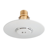
the Enclosure and the Cover Plate, to
ensure separation of the two pieces
when the solder melts.
Solder having a temperature rating of
135°F/57°C is used with Cover Plate
Assemblies for the 135°F/57°C and
155°F/68°C sprinklers, and solder with
a temperature rating of 165°F/74°C is
used with Cover Plate Assemblies for
the 175°F/79°C and 200°F/93°C sprin-
klers (Ref. Table 1). When the Cover
Plate Assembly is exposed to a tem-
perature sufficient to fuse the solder,
the Cover Plate will fall away from the
Enclosure which allows the Deflector
to drop into position and, to expose the
Sprinkler for operation.
A label located on the side of the Cover
Plate Assembly indicates the tempera-
ture rating of the Cover Plate Assem-
blyandthetemperatureratingofthe
F690Sprinklerwithwhichitistobe
used.
INSTALLATION
NOTES
Do not install any bulb type sprinkler
if the bulb is cracked or there is a loss
ofliquidfromthebulb.Withthesprin-
kler held horizontally, a small air
bubble should be present. The diame-
teroftheairbubblevariesfromap-
proximately1/16inch(1,6mm)for
the 135°F/57°C rating to 3/32 inch
2,4 mm) for the 200° F/93°C rating.
Only use the Model 2111 Sprinkler
Wrench for installation of the F690
Sprinkler. Do not wrench on the
Sprinkler other than as shown in Fig-
ure D.
Do not attempt to make-up for insuf-
ficient adjustment in the Sprinkler
Assemblyby under- orover-tightening
the Sprinkler/Mounting Cup Assem-
bly.Readjust theposition of thesprin-
kler fitting to suit.
A leak tight 1/2 inch NPT sprinkler
joint should beobtainedwith atorque
of 7to 14ft.lbs.(9,5to 19,0Nm).More
than 21 ft. lbs. (28,5 Nm) of torque
may distort the sprinkler orifice seat
with consequent leakage.
Proceed with the installation as fol-
lows:
1. The pipe connected to the sprinkler
fitting should be cut so that the bot-
tom face of the fitting is between
1-15/16 and 2-3/16 inch (49,2 mm
and 55,6 mm) above the ceiling line.
By using a 1/4 inch (6,4 mm) range
for the “D” dimension, the remaining
1/4 inch (6,4 mm) of adjustment can
be used to compensate for the pos-
sible manufacturing variations in the
make-in of the sprinklers and the
take-out of fittings (as permitted by
ANSI B1.20.1).
FIGURE C
NOMINAL DISCHARGE CURVES
FIGURE D
MODEL 2111 SPRINKLER WRENCH
FIGURE E
PROTECTIVE CAP