TFP110 0
Page 8 of 16
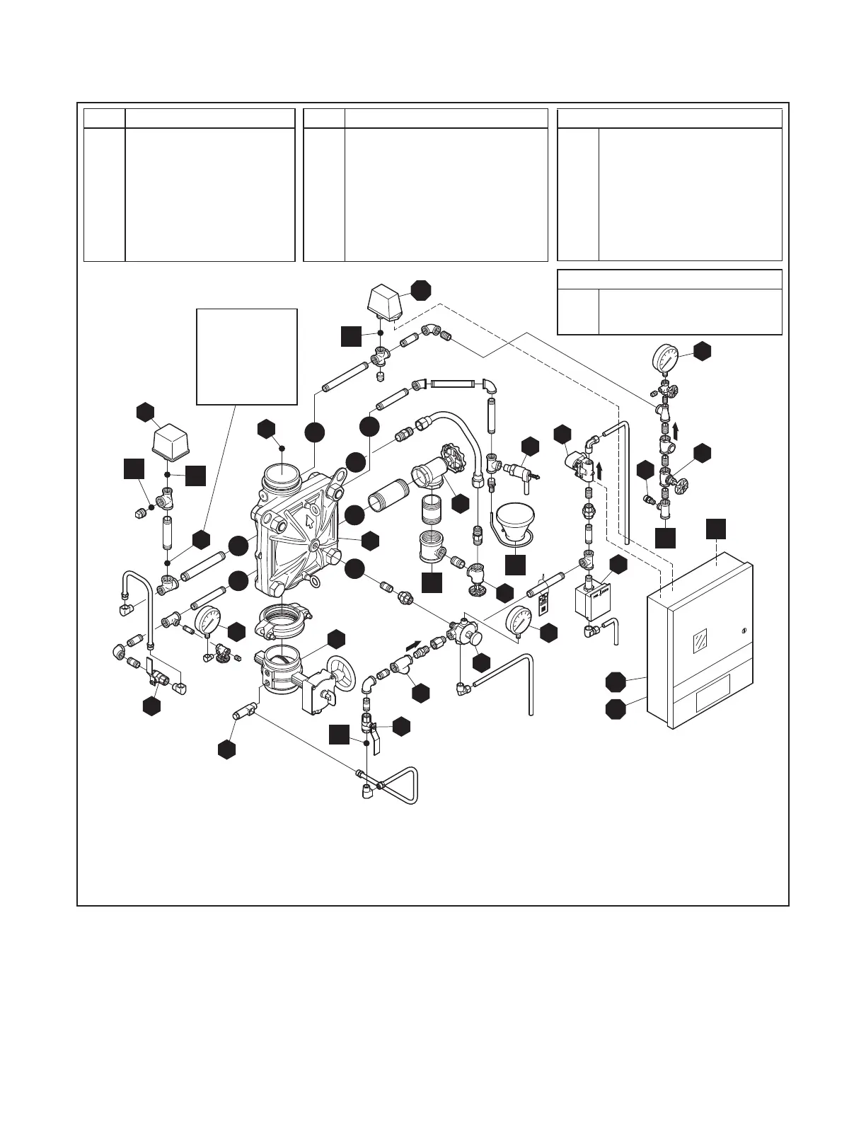
External Trim Connections
C1
C2
C3
C4
C5
C6
C7
C8
Diaphragm Supply Connection
Water Motor Alarm Connection
Air Supply Connection
Waterow Pressure Alarm Switch
Connection
Low Air Pressure Switch
Connection
Main Drain Connection
Drip Funnel Drain Connection
Fire Detection System
Connection
Item Description
A
B
C
D
E
F
G
H
J
K
L
DV-5a Valve
System Main Control Valve
Waterow Pressure Switch
Main Drain Valve
System Drain Valve
Automatic Drain Valve
Alarm Test Valve
Alarm Control Valve (Optional)
Water Supply Gauge
Diaphragm Gauge
System Gauge
Item Description
M
N
P
Q
R
S
T
U
V
W
X
Manual Control Station
Manual Reset Actuator
Diaphragm Supply Valve
Diaphragm Supply Strainer
Water Supply Shut-Off
Air Supply Valve
Air Pressure Relief Valve
Not Used
Solenoid Valve
Not Used
System Shut-Off Valve
QRS Equipment
Q1
Q2
Q3
QRS Switch
Releasing Panel
Battery Back-Up
LOCATION
FOR OPTIONAL
ELECTRICALLY
SUPERVISED
N.O. ALARM
CONTROL
VALVE
C6
C7
C5
C3
C2
C4
C1
C8
Q1
Q2
Q3
A
B
J
K
D
E
F
G
M
N
P
Q
V
X
S
L
T
C
H
R
P1
P6
P7
P2
P3
P4
P5
FIGURE 3B
DV-5a VALVE - DOUBLE INTERLOCK PREACTION ELECTRIC/ELECTRIC ACUATION TRIM
WITH MODEL QRS ELECTRONIC ACCELERATOR OPTIONAL COMPONENTS
OPERATIONAL COMPONENTS
Notes:
• Port Connections P1 through P7 are described in Technical Data Sheet TFP1450, Figure 2.