2
Elite Control Installation Instructions
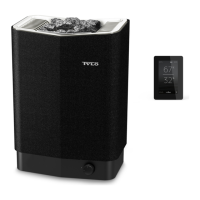
The control panel can be installed inside or outside the sauna room. If the control is installed inside
the room, install no higher than 3’ (90 cm) above the oor. No closer than 12” (30 cm) to heater.
Installation without Mounting Bracket
Cut a 1-3/16” (3 cm) hole through the wall big enough for the control panel connector.
Attach the double-sided adhesive to the control panel. Before applying the control to the wall, con-
nect it to the heater and electrically test everything rst. Clean the surface where the control will be
applied to remove all dust. Remove the protective backing from the adhesive. Silicone sealant can
be applied in the groove on the back of the panel as an extra seal. Connect the control wire, push the
excess wire through the hole in the wall and press the control panel rmly to the wall.
Installation with Bracket
Use the mounting bracket as a template to mark screws holes on the wall. Tighten the screws a little
until the bracket is nearly secured.
Remove the bracket from the wall. Use adhesive to mount the control to the bracket. Remember to
position the switch according to the picture.
Control stuck directly to the wall.
Control cable in the stud cavity.
Installation without Bracket Installation with Bracket
Generally only used when control wire is surface
mounted; i.e. solid log style outdoor sauna.
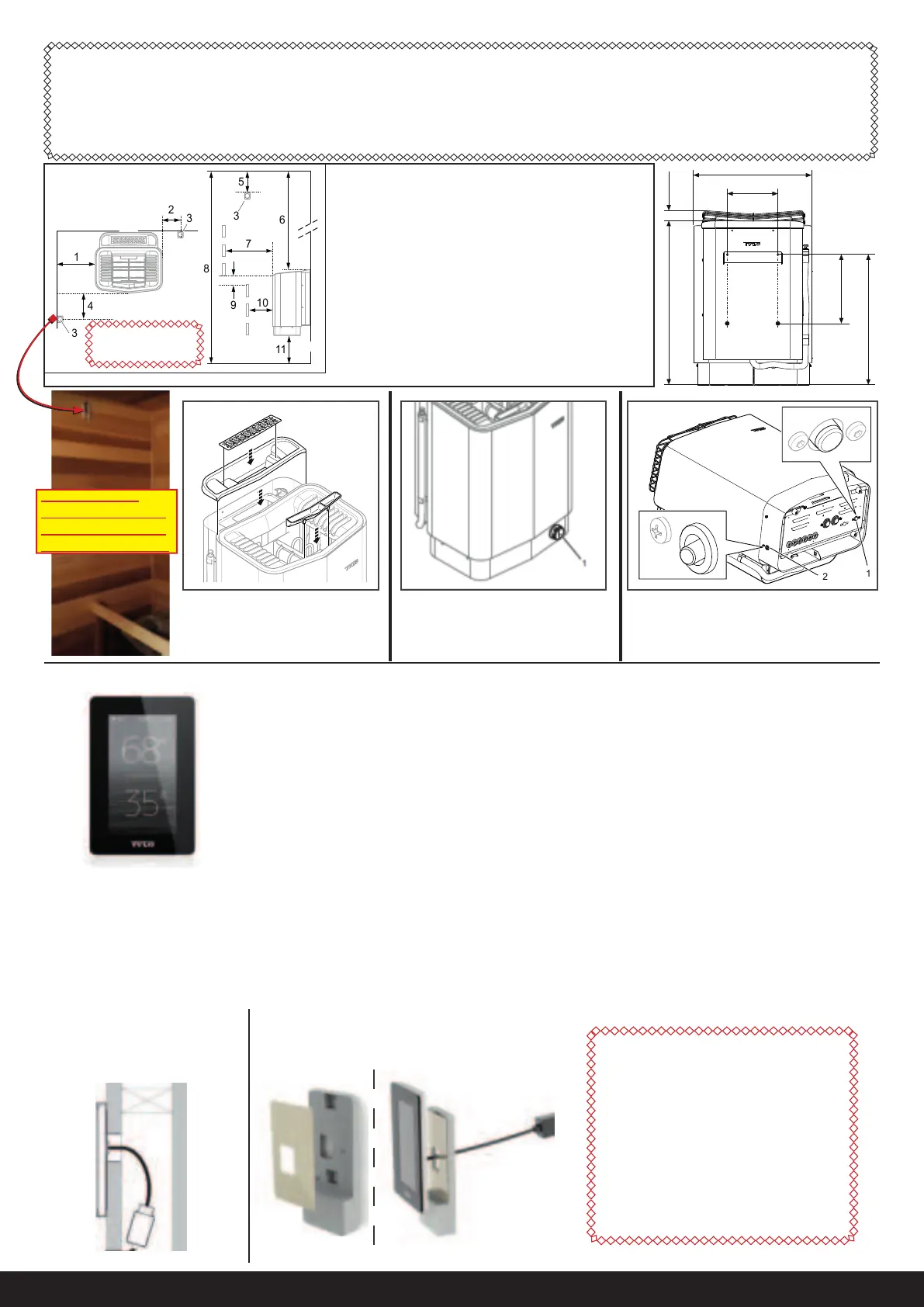
Elite Control Location
The control panel can be
installed inside or outside
of the sauna room.
(Outside is Typical)
Figure 3: Position the sensor according the picture.
18.5 mm
7-5/16"
49 mm
19-5/16 "
462 mm
24-3/8 "
28 mm
11"
43 mm
17 "
4 mm
1-9/16 "
1. Minimum distance from side wall: 4” (100 mm)
2. Sensor position alt 1: 3” (75 mm) from heater
3. Sensor
4. Sensor position alt 2: 3” (75 mm) from heater front
5. Sensor position: 1” (25 mm) from ceiling
6. Minimum distance from ceiling: 44” (1100 mm)
7. Minimum distance from heater guard: 4” (100 mm)
8. Minimum ceiling height: 75” (1900 mm)
9. Minimum distance: 1” (25 mm)
10. Minimum distance from heater guard: 2” (50 mm)
11. Distance from oor: 7” (175 mm)
** Combi Elite Control distance to heater is max 75 feet
Fig. 9: Resetting the temperature cut-out
1. Temperature cut-out water reservoir
2. Temperature cut-out sauna heater
To prevent build up of lime-scale
and higher salt/mineral levels,
empty the reservoir after each
use. If this is not done and wa-
ter is added each time you take
a sauna, foam build-up could
occur which can cause the level
sensor to detect a higher water
level than usual. There is a risk
the heating element may break.
1. CAUTION: Heater junction box can be a tight t. Make sure no bare wires come in to contact with circuit board, on/o switch
or any other heater components. Extra care should be taken when closing junction box cover to ensure wires are not being pushed
out of position.
2. Some prefer or are required to make a weather-proof connection. If so, you may use Liquid tight conduit for the wire exposed
within the sauna. For more exibility, you can install weather proof junction box inside sauna below heater and use exible SOOW
wire to connect to heater
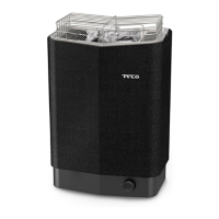
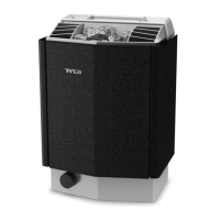
Figure 14: Fitting the cover
for the water reservoir, herb
grille and fragrance holder/air
humidier
Sensor Location:
3” from heater,
1” down from ceiling
1 in.
4 in.
3 in.
7 in.
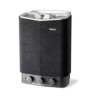
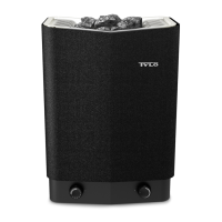
Main Power Switch: On/O Knob
comes packed inside rock tray.
Field install. Turn knob to turn on
heater.
sensor location:
1” down from ceiling
3” to front or side of
heater; not in corner.
 Loading...