NINA-B1 series - System Integration Manual
UBX-15026175 - R06 System description
Page 10 of 48
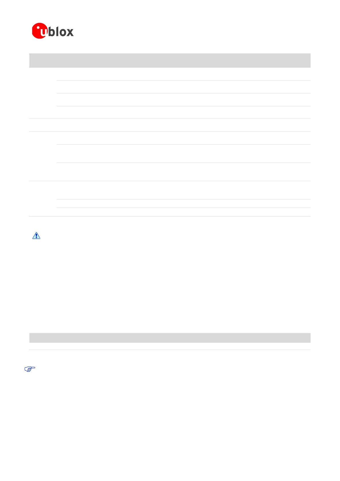
Function Pin Name Pin No.
nR52
pin
Type Description u-blox connectivity software
Pin is analog capable
UART data input
General purpose I/O
Pin is analog capable
General purpose I/O
Pin is analog capable
General purpose I/O
Pin is analog capable
Control
System reset input
Active low
Radio
Tx/Rx antenna interface
Used with NINA-B111 modules
8
28
P0.09
I/O
May be used as a GPIO
9
29
P0.10
I/O
May be used as a GPIO
Other
Serial Wire debug trace data
output
System status signal
SWDCLK
I Serial Wire Debug port clock signal
SWDIO
I/O Serial Wire Debug port data signal
Table 2: NINA-B1 pin description
Do not apply any Voltage to Digital, Control and Radio signal groups while in Non-powered
mode to avoid damaging the module.
1.3 Supply interfaces
1.3.1 Main supply input
The NINA-B1 series uses an integrated DC/DC converter to transform the supply voltage presented at the VCC
pin into a stable system core voltage. Due to this, the NINA-B1 modules are compatible for use in battery
powered designs.
While using NINA-B1 with a battery, it is important that the battery type can handle the peak power of the
module. In case of battery supply, consider adding extra capacitance on the supply line to avoid capacity
degradation. See the NINA-B1 series Data Sheet [2] for information about voltage supply requirement and
current consumption.
Table 3: Summary of voltage supply requirements
The current requirement in Table 3 considers using the u-blox connectivity software with UART
comunication. But it does not include any aditional I/O current. Any use of external push-buttons, LEDs, or
other interfaces will add to the total current consumption of the NINA-B1 module. The peak current
consumption of the entire design will have to be taken into account when considering a battery powered
solution.
1.3.2 Digital I/O interfaces reference voltage (VCC_IO)
On the NINA-B1 series modules, the I/O voltage level is the same as the supply voltage and VCC_IO is internally
connected to the supply input VCC.
Rail Voltage requirement Current requirement (peak)
VCC 1.7 V – 3.6 V
15 mA

 Loading...


