NINA-B1 series - System Integration Manual
UBX-15026175 - R06 System description
Page 7 of 48
- PU = Internal Pull-Up
- PD = Internal Pull-Down
- H = High-Impedance pin
- RF = Radio interface
6. SIGNAL NAME: The signal name for that pin in the mode being used
7. REMARKS: Pin description and notes.
1.2.2 Pin description
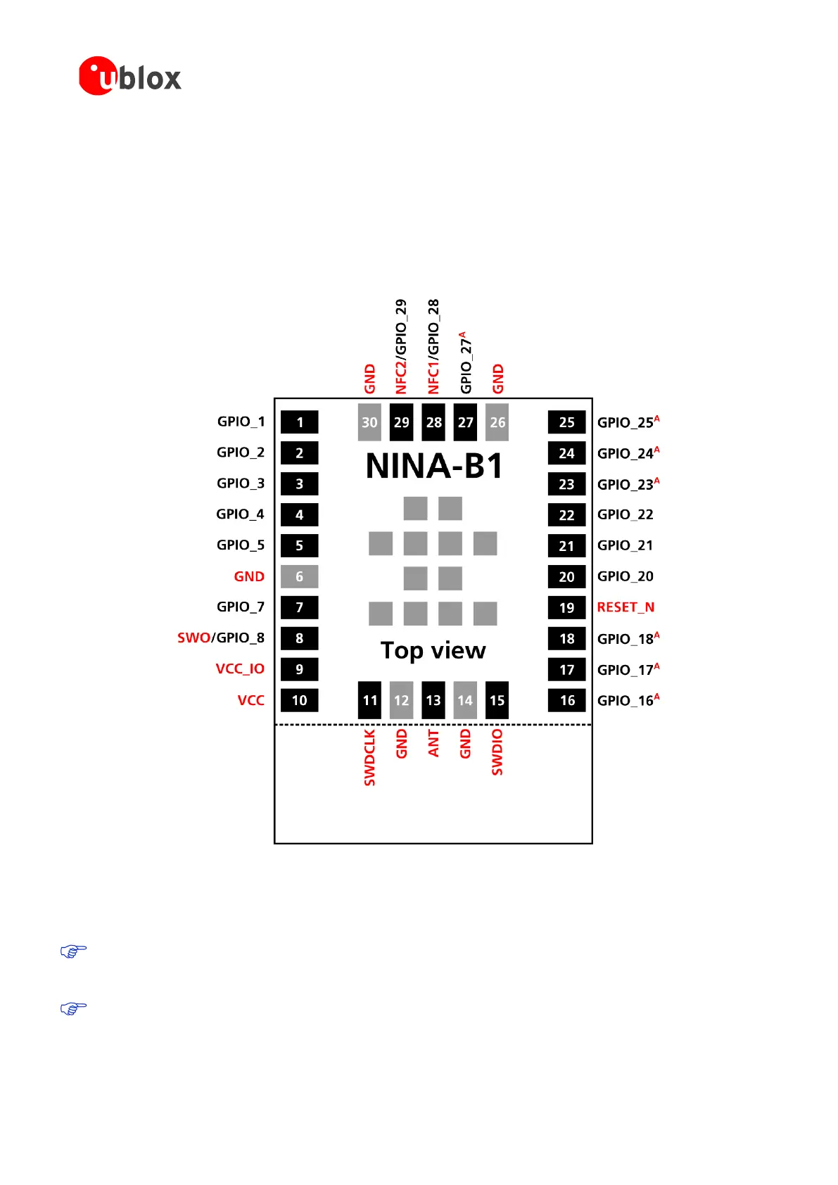
The pin-out described in Figure 2 is an example pin-out that demonstrates the most commonly used interfaces.
A = Analog function capable pin
Figure 2: NINA-B1 series pin assignment (top view)
The grey pins in the center of the modules are GND pins. The outline of NINA-B111 ends at the dotted line as
shown in Figure 2, where the antenna area of NINA-B112 begins.
All digital or analog functions described in this manual can be freely assigned to any GPIO pin. Analog
functions are limited to analog capable pins. Signals marked red in Figure 2 are not freely assignable but
locked to a specific pin.
The GPIO pins 16, 17, 18, and 20 are connected to pins located close to the radio part of the RF chip. It is
recommended to avoid using these pins for high speed digital interfaces or sinking/sourcing large currents
through them. Doing so, can affect the RF performance.

 Loading...


