SARA-G3 series - System Integration Manual
UBX-13000995 - R06 Objective Specification Design-in
Page 133 of 218
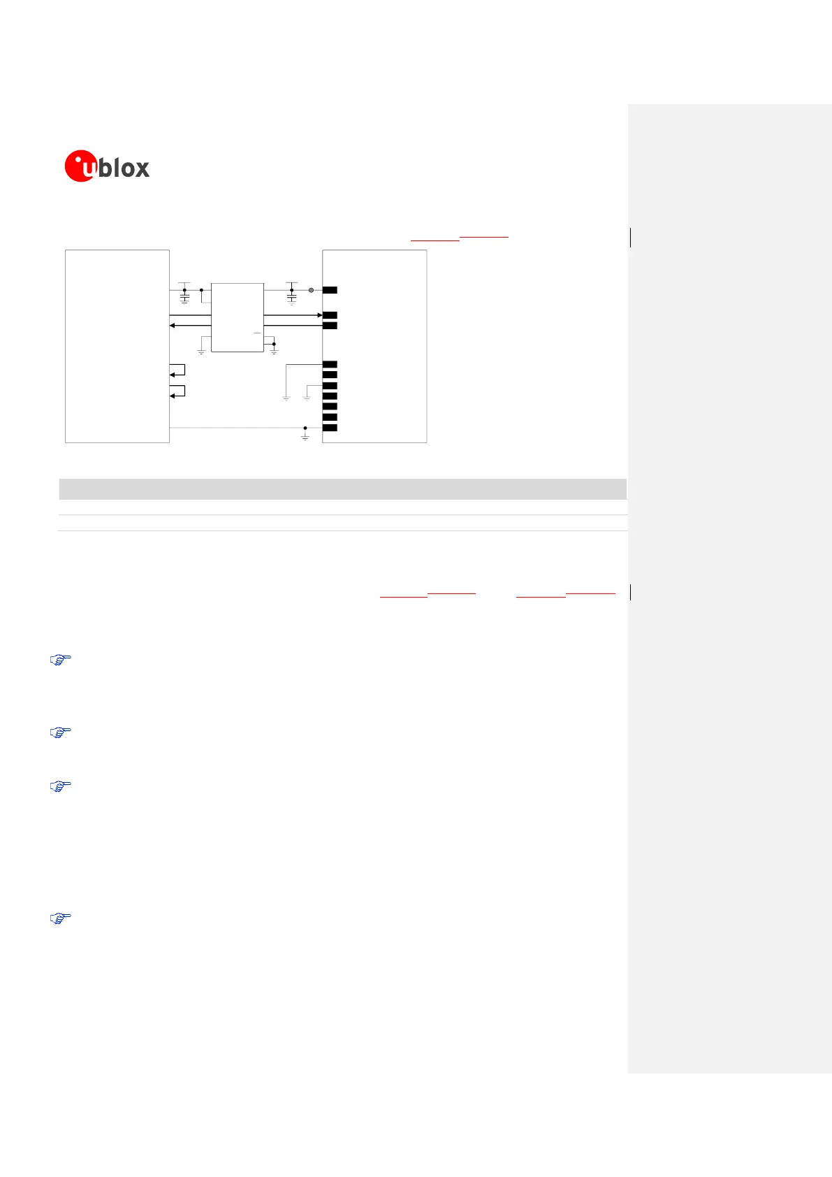
If a 3.0 V Application Processor is used, appropriate unidirectional voltage translators must be provided
using the module V_INT output as 1.8 V supply, as described in Figure 52Figure 52.
4
V_INT
TxD
Application Processor
(3.0V DTE)
RxD
DTR
DSR
RI
DCD
GND
SARA-G3 series
(1.8V DCE)
12
TXD
9
DTR
13
RXD
6
DSR
7
RI
8
DCD
GND
1V8
B1 A1
GND
U1
VCCBVCCA
Unidirectional
Voltage Translator
C1
C2
3V0
DIR1
DIR2 OE
VCC
B2 A2
RTS
CTS
11
RTS
12
CTS
TP
Figure 52: UART interface application circuit with partial V.24 link (3-wire) in DTE/DCE serial communication (3.0 V DTE)
Part Number - Manufacturer
100 nF Capacitor Ceramic X7R 0402 10% 16 V
GRM155R61A104KA01 - Murata
Unidirectional Voltage Translator
SN74AVC2T245 - Texas Instruments
Table 29: Component for UART application circuit with partial V.24 link (3-wire) in DTE/DCE serial communication (3.0 V DTE)
If only TXD and RXD lines are provided, as described in Figure 51Figure 51 or in Figure 52Figure 52,
and HW flow-control is disabled (AT&K0), the power saving must be enabled by AT+UPSV=1. In this
way, the UART of the module is re-enabled 20 ms after a low-to-high transition on the TXD input line,
and the recognition of the subsequent characters is guaranteed until the module is in active-mode.
Data delivered by the DTE can be lost using this configuration and the following settings:
o HW flow-control enabled in the module (AT&K3, that is the default setting)
o Module power saving enabled by AT+UPSV=1
o HW flow-control disabled in the DTE
In this case the first character sent when the module is in idle-mode will be a wake-up character
and will not be a valid communication character (refer to section 1.9.1.4 for the complete
description).
If power saving is enabled the application circuit with the TXD and RXD lines only is not
recommended. During command mode the DTE must send to the module a wake-up character or a
dummy “AT” before each command line (refer to section 1.9.1.4 for the complete description), but
during data mode the wake-up character or the dummy “AT” would affect the data communication.
Additional considerations
Any external signal connected to the UART interface must be tri-stated or set low when the module
is in power-down mode and during the module power-on sequence (at least until the activation of
the V_INT supply output of the module), to avoid latch-up of circuits and allow a proper boot of
 Loading...