MAX-7 / NEO-7 - Hardware Integration Manual
UBX-13003704 - R09 Production Information Hardware description
Page 13 of 52
behavior. After every byte is read from register 0xFF the internal address counter is incremented by one,
saturating at 0xFF. Therefore, subsequent reads can be performed continuously.
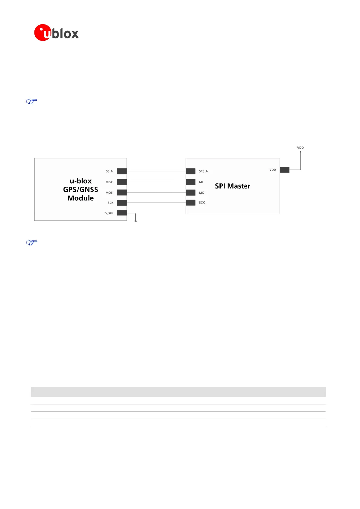
2.6.4 SPI (NEO-7)
With NEO-7 modules, an SPI interface is available for communication to a host CPU.
SPI is not available in the default configuration, because its pins are shared with the UART and DDC
interfaces. The SPI interface can be enabled by connecting D_SEL to ground (NEO-7) (see section 2.7.3).
For speed and clock frequency see the Data Sheet.
Figure 4 shows how to connect a u-blox GNSS receiver to a host/master. The signal on the pins must meet the
conditions specified in the Data Sheet.
Figure 4: Connecting to SPI Master
VCC_IO must have the same voltage level as the host.
2.7 I/O pins
2.7.1 RESET_N: Reset input
Driving RESET_N low activates a hardware reset of the system. Use this pin only to reset the module. Do not use
RESET_N to turn the module on and off, since the reset state increases power consumption. With u-blox 7
RESET_N is an input only.
2.7.2 EXTINT: External interrupt
EXTINT is an external interrupt pin with fixed input voltage thresholds with respect to VCC or VCC_IO (see the
data sheet for more information). It can be used for wake-up functions in Power Save Mode on all u-blox 7
modules and for aiding. Leave open if unused.
2.7.3 D_SEL: Interface select (NEO-7)
The D_SEL pin, available on all NEO-7 modules, selects the available interfaces. SPI cannot be used
simultaneously with UART/DDC.
If open, UART and DDC are available. If pulled low, the SPI Interface is available.
Table 3: D_SEL pin on NEO-7