MAX-8 / MAX-M8 - Hardware Integration Manual
UBX-15030059 - R05 Design Page 12 of 31
Production Information
2.4 Antenna and Antenna supervision
The MAX-8 / MAX-M8 modules are designed for usage with an active antenna, see section 2.4.2
2.4.1 Antenna design with passive antenna
☞ A passive antenna can be used, but require an external LNA and SAW for best performance.
A design using a passive antenna requires more attention to the layout of the RF section. Typically, a
passive antenna is located near electronic components; therefore, care should be taken to reduce
electrical noise that may interfere with the antenna performance. Passive antennas do not require a
DC bias voltage and can be directly connected to the RF input pin RF_IN. Sometimes they may also
need a passive matching network to match the impedance to 50 Ω.
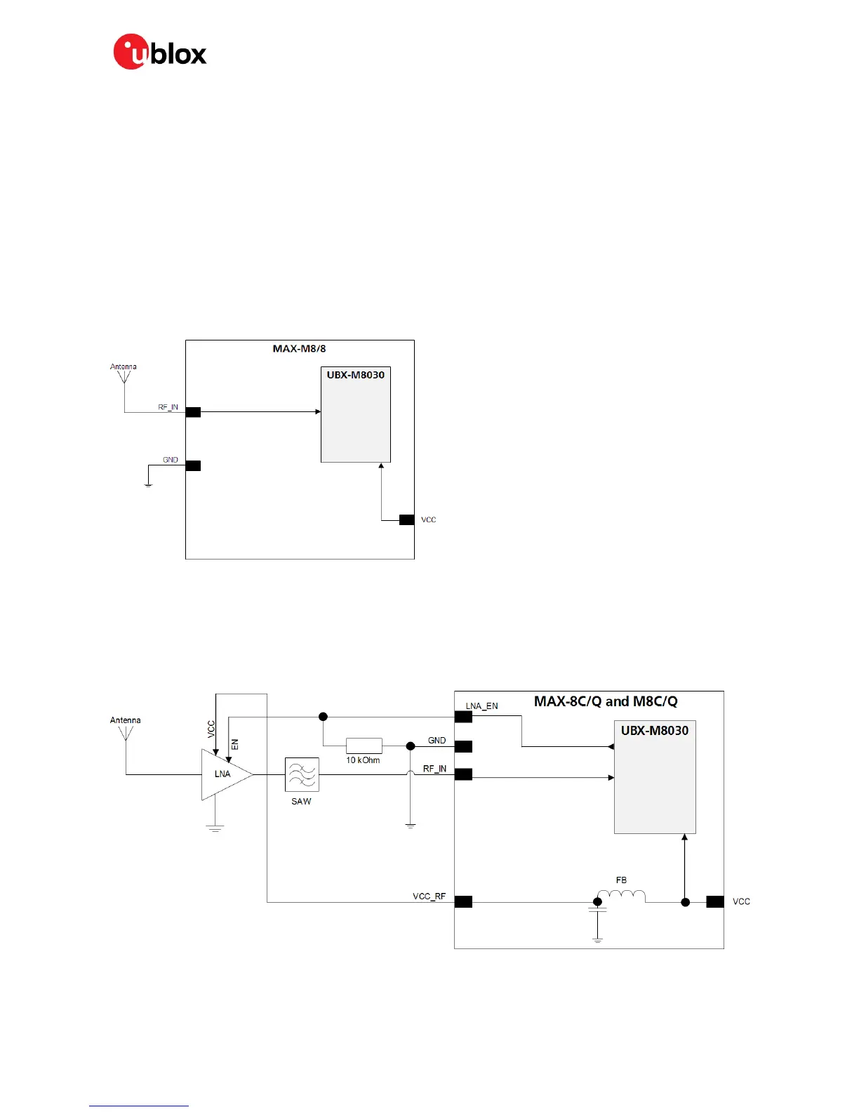
Figure 6 shows a minimal setup for a design with a good GNSS patch antenna.
Figure 6: Module design with passive antenna (for exact pin orientation see
MAX-8 Data Sheet
[1]
and
MAX-M8 Data Sheet
[2])
☞ Use an antenna that has sufficient bandwidth to receive all GNSS constellations. See Appendix.
Figure 7 shows a design using an external LNA and SAW to increase the sensitivity for best
performance with passive antenna.
Figure 7: MAX-8C/Q and M8C/Q modules design with passive antenna and an external LNA and SAW (for exact pin
orientation see the
MAX-8 Data Sheet
[1]
and
MAX-M8 Data Sheet
[2])

 Loading...


