MAX-8 / MAX-M8 - Hardware Integration Manual
UBX-15030059 - R05 Hardware description Page 9 of 31
Production Information
1.5.6 ANT_DET: Open Circuit Detection (MAX-M8)
Antenna open circuit detection (ANT_DET) is not activated by default on the MAX-8 / MAX-M8
modules. ANT_DET can be mapped to PIO13 (EXTINT).
ANT_DET is an input used to report whether an external circuit has detected an external antenna or
not.
"high" = Antenna detected (antenna consumes current); "low" = Antenna not detected (no current
drawn).
Antenna supervision is configurable using message UBX-CFG-ANT.
☞ Refer to the
u-blox 8 /
u-blox M8 Receiver Description Including Protocol Specification
[3] for
information about further settings.
1.6 Electromagnetic interference on I/O lines
Any I/O signal line with a length greater than approximately 3 mm can act as an antenna and may pick
up arbitrary RF signals transferring them as noise into the GNSS receiver. This specifically applies to
unshielded lines, in which the corresponding GND layer is remote or missing entirely, and lines close
to the edges of the printed circuit board.
If, for example, a cellular signal radiates into an unshielded high-impedance line, it is possible to
generate noise in the order of volts and not only distort receiver operation but also damage it
permanently.
On the other hand, noise generated at the I/O pins will emit from unshielded I/O lines. Receiver
performance may be degraded when this noise is coupled into the GNSS antenna (see Figure 19).
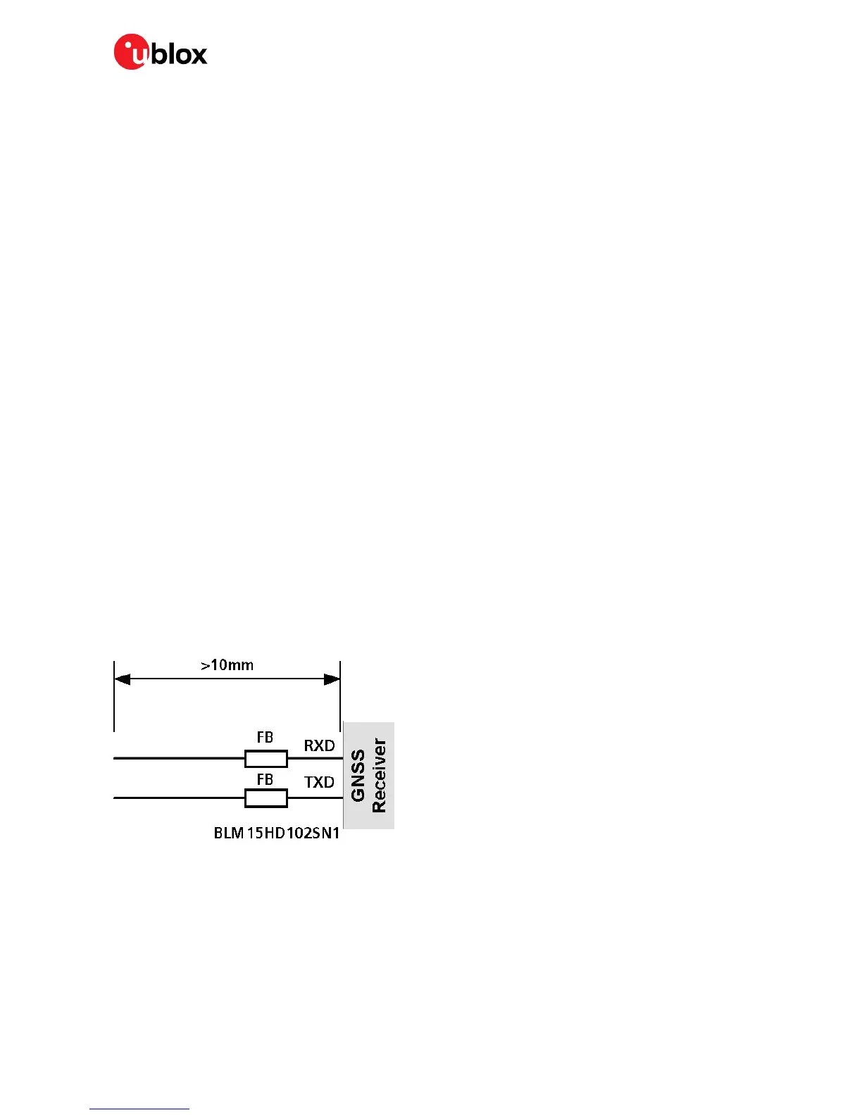
To avoid interference by improperly shielded lines, it is recommended to use resistors (e.g. R>20 Ω),
ferrite beads (e.g. BLM15HD102SN1) or inductors (e.g. LQG15HS47NJ02) on the I/O lines in series.
These components should be chosen with care because they will affect also the signal rise times.
Figure 2 shows an example of EMI protection measures on the RX/TX line using a ferrite bead. More
information can be found in section 4.3.
Figure 2: EMI Precautions

 Loading...


