MAX-8 / MAX-M8 - Hardware Integration Manual
UBX-15030059 - R05 Design Page 15 of 31
Production Information
Abbreviation Description
AC Active Antenna Control enabled
SD Short Circuit Detection Enabled
OD Open Circuit Detection enabled
PDoS Short Circuit Power Down Logic enabled
SR Automatic Recovery from Short state
Table 4: Active Antenna Supervisor Message on startup (UBX binary protocol)
☞ To activate the antenna supervisor use the UBX-CFG-ANT message. For further information, see
the
u-blox 8 / u-blox M8 Receiver Description Including Protocol Specification
[3].
Similar to the antenna supervisor configuration, the status of the antenna supervisor will be reported
in an NMEA ($GPTXT) or UBX (INF-NOTICE) message at start-up and on every change.
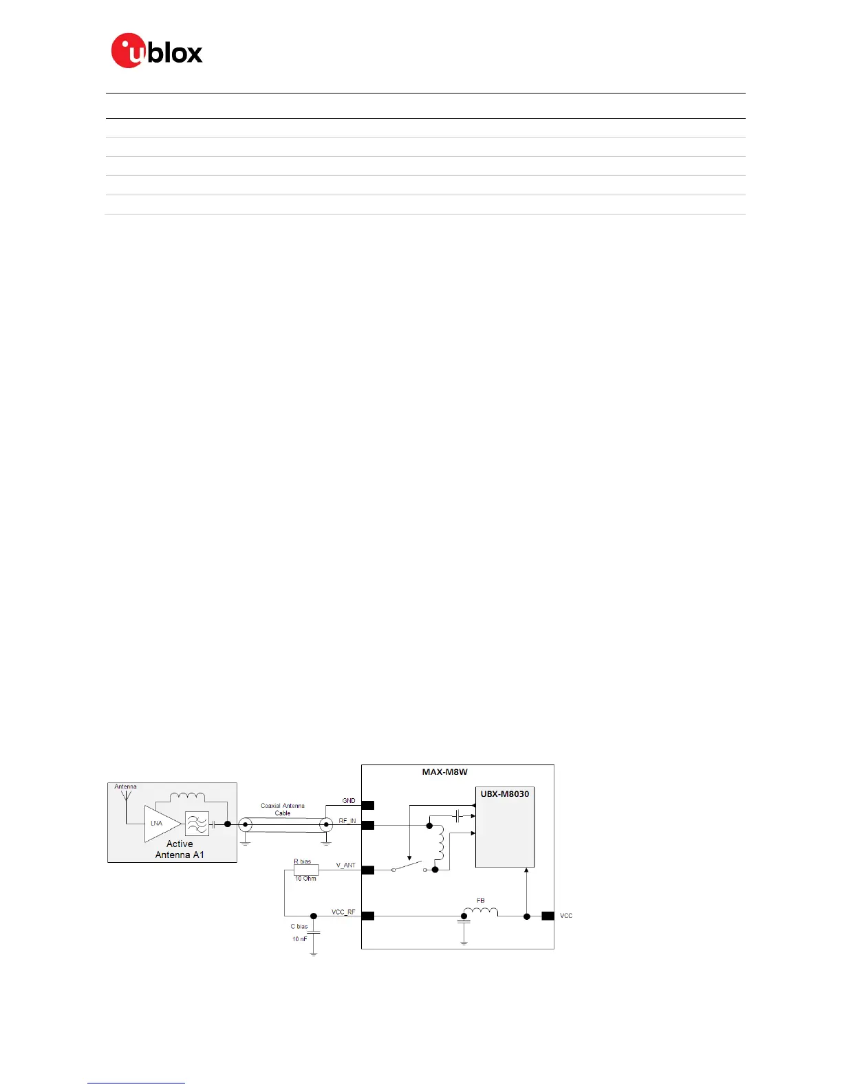
2.4.5 Power and short detection antenna supervisor (MAX-M8W)
If a suitably dimensioned series resistor R_BIAS is placed in front of pin V_ANT, a short circuit can be
detected in the antenna supply. This is detected inside the u-blox MAX-M8W module and the antenna
supply voltage will be immediately shut down. After which, periodic attempts to re-establish antenna
power are made by default.
An internal switch (under control of the receiver) can turn off the supply to the external antenna
whenever it is not needed. This feature helps to reduce power consumption in power save mode.
☞ To configure the antenna supervisor, use the UBX-CFG-ANT message. For further information,
see the u-blox 8 /
u-blox M8 Receiver Description Including Protocol Specification
[3].
⚠ Short circuits on the antenna input without limitation (R_BIAS) of the current can result in
permanent damage to the receiver! Therefore, it is mandatory to implement an R_BIAS in all risk
applications, such as situations where the antenna can be disconnected by the end-user or that
have long antenna cables.
☞ If VCC_RF voltage does not match with the antenna supply voltage, use a filtered external supply,
as shown in Figure 13.
Supply from VCC_RF (MAX-M8W)
Figure 11 shows an active antenna supplied from the u-blox MAX-M8W module.
The VCC_RF pin can be connected with V_ANT to supply the antenna. Note that the voltage
specification of the antenna has to match the actual supply voltage of the u-blox module (e.g. 3.0 V).
Figure 11: MAX-M8W module design with active antenna, internal supply from VCC_RF (for exact pin orientation, see the
MAX-M8 Data Sheet
[2])

 Loading...


