MAX-8 / MAX-M8 - Hardware Integration Manual
UBX-15030059 - R05 Design Page 11 of 31
Production Information
2.2 Minimal design
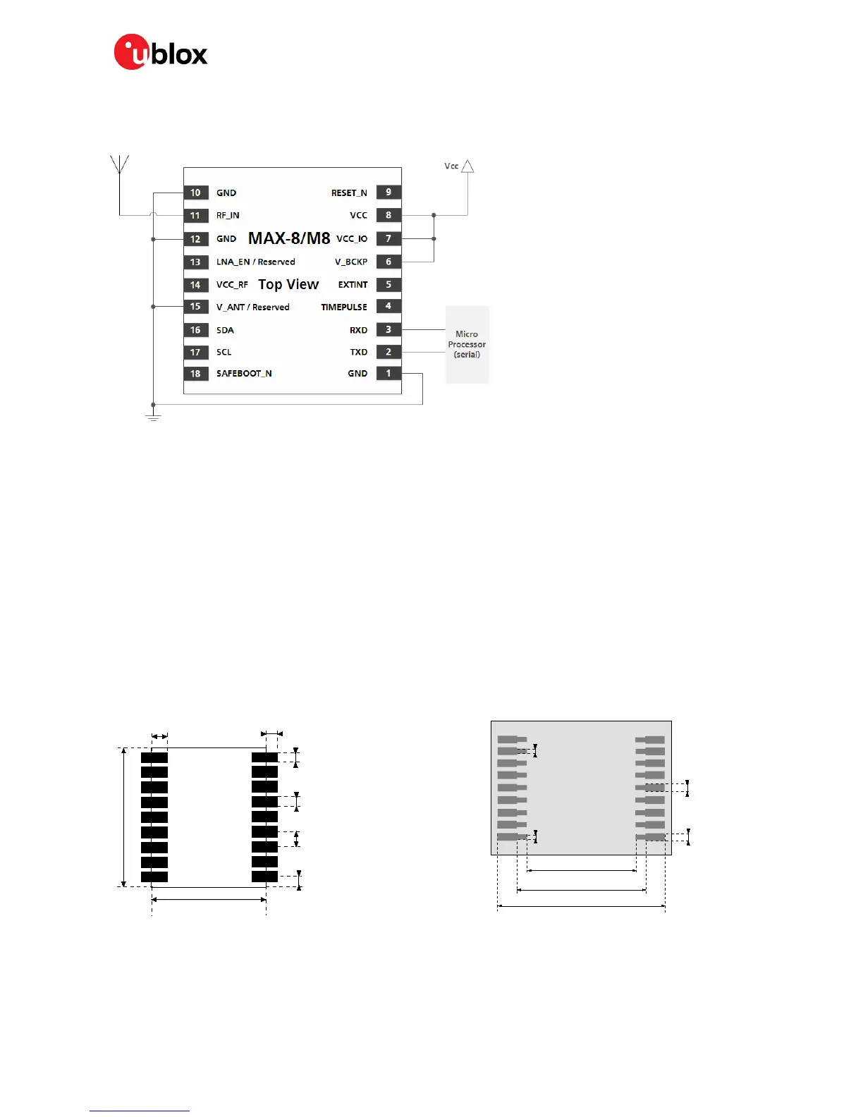
This is a minimal setup for a MAX-8 / M8 GNSS receiver:
Figure 3: MAX-8 / MAX-M8 passive antenna design
☞ For information on increasing immunity to jammers such as GSM, see section 4.3.
2.3 Layout: Footprint and paste mask
Figure 4 describes the footprint and provides recommendations for the paste mask for MAX-8 / MAX-
M8 LCC modules. These are recommendations only, and not specifications. Note that the copper and
solder masks have the same size and position.
To improve the wetting of the half vias, reduce the amount of solder paste under the module and
increase the volume outside of the module by defining the dimensions of the paste mask to form a T-
shape (or equivalent) extending beyond the copper mask. For the stencil thickness, see section 4.2
.
☞ Consider the paste mask outline when defining the minimal distance to the next component. The
exact geometry, distances, stencil thicknesses and solder paste volumes must be adapted to the
specific production processes (e.g. soldering) of the customer.
Figure 5: MAX-8 / MAX-M8 paste mask
☞ MAX Form Factor (10.1 x 9.7 x 2.5): Same Pitch as NEO for all pins: 1.1 mm, but 4 pads in each
corner (pin 1, 9, 10 and 18) only 0.7 mm wide instead 0.8 mm

 Loading...


