SARA-G3 and SARA-U2 series - System Integration Manual
UBX-13000995 - R26 System description
Page 37 of 217
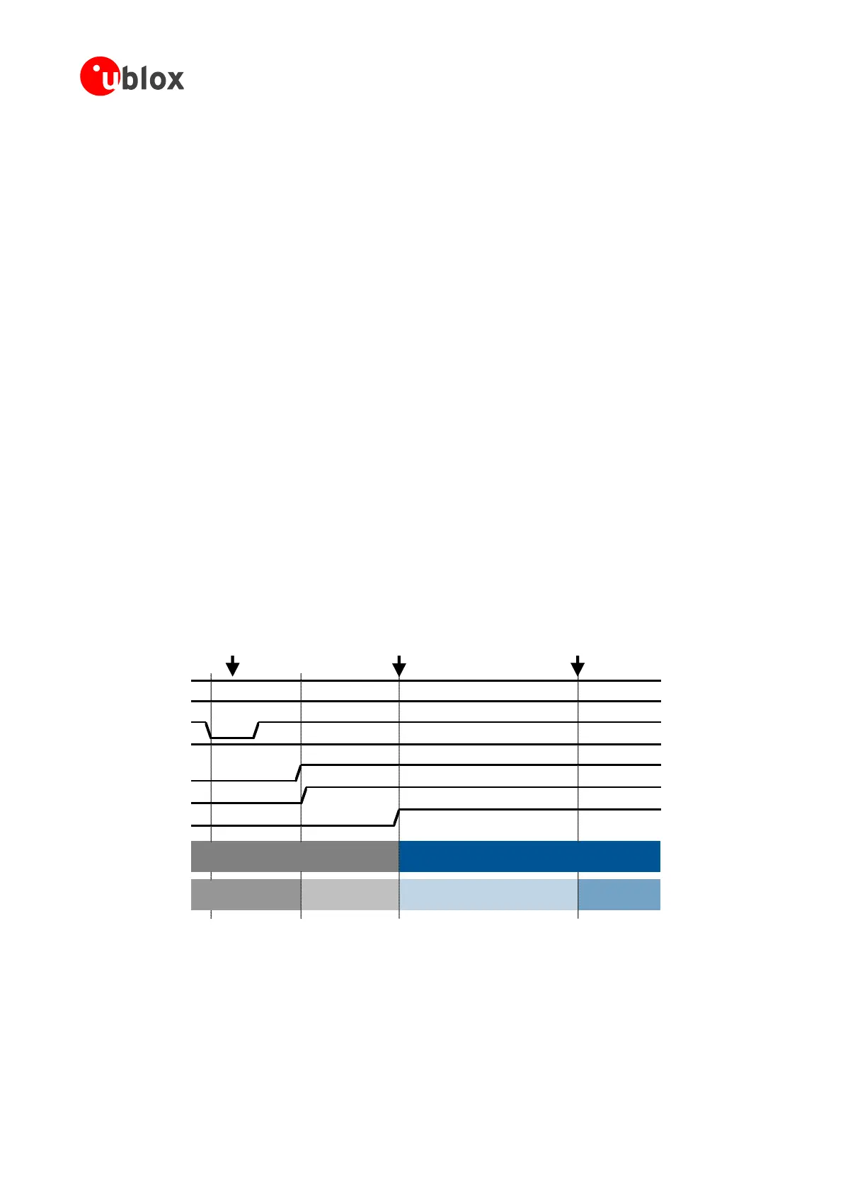
1.6.1.3 Switch-on sequence from power-off mode
Figure 22 shows the modules power-on sequence from the power-off mode, describing the following phases:
The external supply is still applied to the VCC inputs as it is assumed that the module has been previously
switched off by means of the AT+CPWROFF command: the V_BCKP output is internally enabled as proper
VCC is present, the RESET_N of SARA-U2 series is set to high logic level due to internal pull-up to V_BCKP,
the PWR_ON is set to high logic level due to external pull-up connected to V_BCKP or VCC.
The PWR_ON input pin is set low for a valid time period, representing the start-up event.
All the generic digital pins of the modules are tri-stated until the switch-on of their supply source (V_INT):
any external signal connected to the generic digital pins must be tri-stated or set low at least until the
activation of the V_INT supply output to avoid latch-up of circuits and allow a proper boot of the module.
The V_INT generic digital interfaces supply output is enabled by the integrated power management unit.
The RESET_N line of SARA-G3 series rises suddenly to high logic level due to internal pull-up to V_INT.
The internal reset signal is held low by the integrated power management unit: the baseband processor core
and all the digital pins of the modules are held in reset state.
When the internal reset signal is released by the integrated power management unit, any digital pin is set in
a proper sequence from the reset state to the default operational state. The duration of this pin’s
configuration phase differs between the generic digital interfaces and the USB interface, due to specific
host / device enumeration timings (see section 1.9.3)
o Generic digital interfaces pin configuration time: 3 seconds typical on SARA-G3 and SARA-U2 series
modules, except for on SARA-U201 modules, which have 4 seconds typical
o USB interface configuration time: 5 seconds typical on SARA-G3 and SARA-U2 series modules, except
for on SARA-U201 modules, which have 6 seconds typical
The module is fully ready to operate after all the interfaces are configured.
VCC
V_BCKP
PWR_ON
SARA-U2 RESET_N
V_INT
SARA-G3 RESET_N
Internal Reset
System State
Digital Pins State
Internal Reset → Operational Operational
Start of interface
configuration
Module interfaces
are configured
Figure 22: SARA-G3 and SARA-U2 series power-on sequence from power-off mode

 Loading...


