SARA-G3 and SARA-U2 series - System Integration Manual
UBX-13000995 - R26 System description
Page 55 of 217
The time period between two paging receptions is defined by the current base station (i.e. by the network):
If the module is registered with a 2G network, the paging reception period can vary from ~0.47 s (DRX = 2,
i.e. 2 x 51 2G-frames) up to ~2.12 s (DRX = 9, i.e. 9 x 51 2G-frames)
If the module is registered with a 3G network, the paging reception period can vary from 0.64 s (DRX = 6,
i.e. 2
6
3G-frames) up to 5.12 s (DRX = 9, i.e. 2
9
3G-frames)
The time period of the UART enable/disable cycle is configured differently when the module is registered with a
2G network compared to when the module is registered with a 3G network:
2G: the UART is synchronously enabled to every paging reception on SARA-G3 modules, whereas the UART
is not necessarily enabled at every paging reception on SARA-U2 modules: the UART is enabled concurrently
to a paging reception, and then, as data has not been received or sent, the UART is disabled until the first
paging reception that occurs after a timeout of 2.0 s, and therefore the interface is enabled again
3G: the UART is asynchronously enabled to paging receptions, as the UART is enabled for ~20 ms, and then,
if data are not received or sent, the UART is disabled for 2.5 s, and afterwards the interface is enabled again
Not registered: when a module is not registered with a network, the UART is enabled for ~20 ms, and then,
if data has not been received or sent, the UART is disabled for ~2.1 s on SARA-G3 modules or for 2.5 s on
SARA-U2 modules, and afterwards the interface is enabled again
The module active mode duration outside an active call depends on:
Network parameters, related to the time interval for the paging block reception (minimum of ~11 ms)
Duration of UART enable time in absence of data reception (~20 ms)
The time period from the last data received at the serial port during the active mode: the module does not
enter idle mode until a timeout expires. The second parameter of the +UPSV AT command configures this
timeout, from 40 2G-frames (i.e. 40 x 4.615 ms = 184 ms) up to 65000 2G-frames (i.e. 65000 x 4.615 ms =
300 s). Default value is 2000 2G-frames (i.e. 2000 x 4.615 ms = 9.2 s)
The active mode duration can be extended indefinitely since every subsequent character received during the
active mode, resets and restarts the timer.
The timeout is ignored only by SARA-U2 modules immediately after AT+UPSV=1 has been sent, so that the
UART interface is disabled and the module may enter idle mode immediately after the AT+UPSV=1 is sent
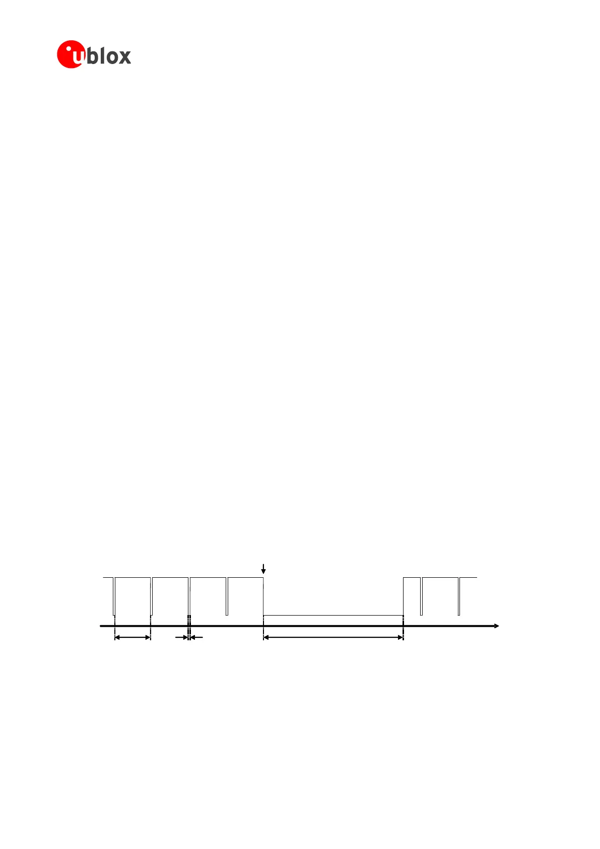
The hardware flow-control output (CTS line) indicates when the UART interface is enabled (data can be sent and
received over the UART), if HW flow control is enabled, as illustrated in Figure 28.
time [s]
CTS ON
CTS OFF
UART disabled
~10 ms (min)
UART enabled
~9.2 s (default)
UART enabled
Data input
0.47- 2.10 s
Figure 28: CTS behavior with power saving enabled (AT+UPSV=1) and HW flow control enabled: the CTS output line indicates
when the UART interface of the module is enabled (CTS = ON = low level) or disabled (CTS = OFF = high level)

 Loading...


