SARA-R5 series - System integration manual
UBX-19041356 - R04 System description Page 16 of 118
C1-Public
The internal GNSS functionality can be concurrently enabled on the SARA-R510M8S modules by the
dedicated +UGPS AT command, as well as the possible external GNSS functionality can be
concurrently enabled using SARA-R500S or SARA-R510S modules by the dedicated +UGPS AT
command.
Then, the SARA-R5 series modules switch from active mode to the low power idle mode whenever
possible, if the low power configuration is enabled by the dedicated +UPSV AT command. The low
power idle mode can last for different time periods according to the specific +UPSV AT command
setting, according to the specific +CEDRXS / +CEDRXRDP AT commands setting, and according to
the concurrent activities executed by the module, as for example according to the concurrent GNSS
activities.
Then, after having enabled the low power configuration by the dedicated +UPSV AT command,
according to the +CPSMS / +UCPSMS AT commands setting, and according to the concurrent
activities executed by the module (for example according to the concurrent GNSS activities),
whenever possible the SARA-R500S and SARA-R510M8S modules can enter the PSM deep-sleep
mode and the SARA-R510S modules can enter the ultra-low power PSM deep-sleep mode.
Once the modules enter the PSM deep-sleep mode (SARA-R500S and SARA-R510M8S modules) or
the ultra-low power PSM deep-sleep mode (SARA-R510S modules), the available communication
interfaces are not functional: a wake up event, consisting in proper toggling of the PWR_ON input line
or the expiration of the “Periodic Update Timer” set by the LTE network, is necessary to trigger the
wake up routine of the modules that subsequently enter back into the active mode.
SARA-R5 series modules can be gracefully switched off by the dedicated +CPWROFF AT command.
☞ See the SARA-R5 series AT commands manual [2], +UPSV, +CEDRXS, +CEDRXRDP, +CPSMS,
+UCPSMS, +UGPS, +CALA, +CPWROFF AT commands, for the possible configurations and
settings of different operating modes.
1.5 Supply interfaces
1.5.1 Module supply input (VCC)
The modules must be supplied via the three VCC pins that represent the module power supply input.
Voltage must be stable, because during operation, the current drawn by the SARA-R5 series modules
through the VCC pins may vary significantly, depending on the operating mode and state (as
described in sections 1.5.1.2, 1.5.1.3, 1.5.1.4 and 1.5.1.5).
It is important that the supply source is able to withstand the average current consumption occurring
during Tx / Rx call at maximum RF power level (see the SARA-R5 series data sheet [1]).
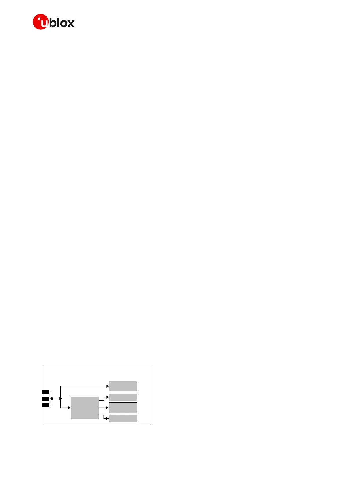
The 3 VCC pins of SARA-R5 series modules are internally connected each other to both the internal
Power Amplifier and the internal baseband Power Management Unit.
Figure 6 provides a simplified block diagram of SARA-R5 series modules’ internal VCC supply routing.

 Loading...


