SARA-R5 series - System integration manual
UBX-19041356 - R04 Design-in Page 74 of 118
C1-Public
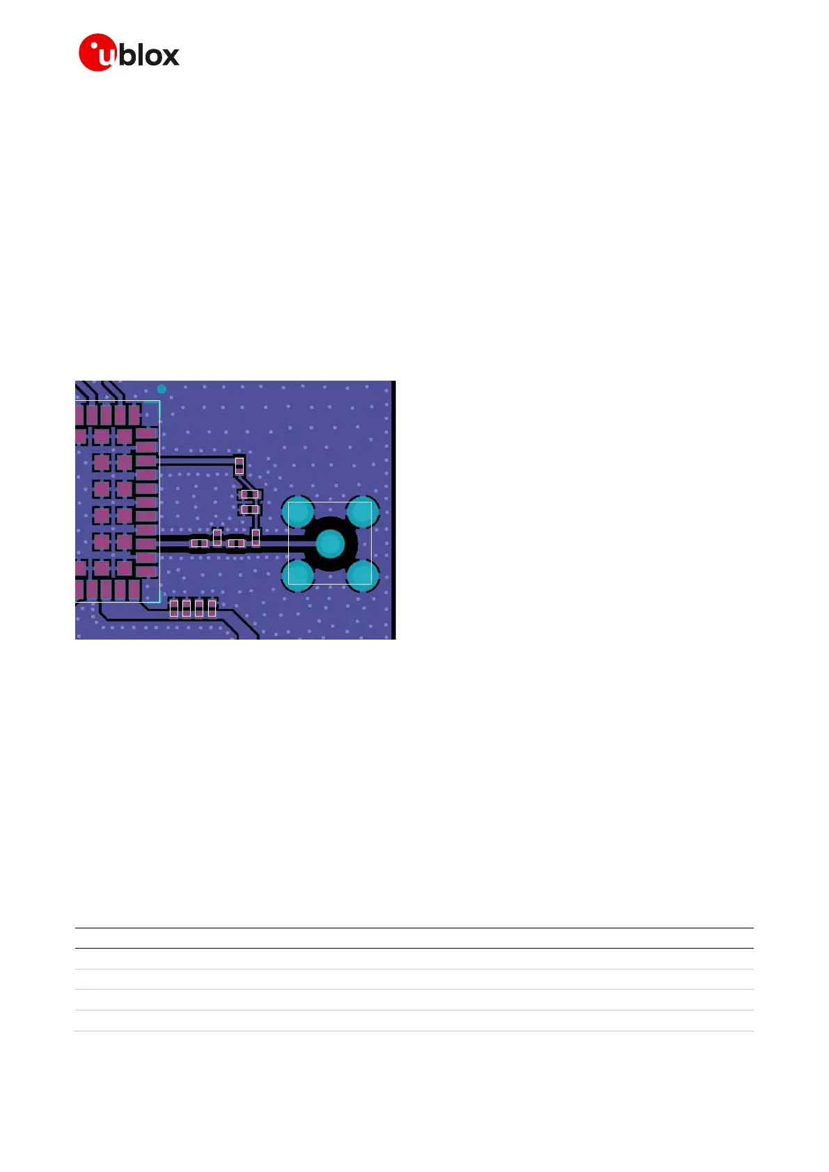
2.4.5.2 Guidelines for ANT_DET layout design
Figure 49 describes the recommended layout for the cellular antenna detection circuit to be provided
on the application board to achieve antenna detection functionality, implementing the recommended
schematic described in the previous Figure 48 and Table 30:
• The ANT pin must be connected to the cellular antenna connector by means of a 50
transmission line, implementing the design guidelines described in section 2.4.2 and the
recommendations of the SMA connector manufacturer.
• DC blocking capacitor at ANT pin (C2) must be placed in series to the 50 RF line.
• The ANT_DET pin must be connected to the 50 transmission line by means of a sense line.
• Choke inductor in series at the ANT_DET pin (L1) must be placed so that one pad is on the 50
transmission line and the other pad represents the start of the sense line to the ANT_DET pin.
• The additional components (R1, C1, D1) on the ANT_DET line must be placed as ESD protection
• The additional high pass filter (C3 and L2) on the ANT line is placed as ESD immunity improvement
SARA module
C2
R1
D1
C1
L1
J1
C3 L2
Figure 49: Suggested layout for antenna detection circuit on application board
2.4.6 Cellular antenna dynamic tuning control interface
SARA-R5 series modules support a wide range of frequencies, from 600 MHz to 2200 MHz. To provide
more efficient antenna designs over a wide bandwidth, I2S_TXD and I2S_WA pins can be configured
to change their output value in real time according to the operating LTE band in use by the module
(see sections 1.11 and 2.8).
These pins, paired with an external antenna tuner IC or RF switch, can be used to:
• tune antenna impedance to reduce power losses due to mismatch
• tune antenna aperture to improve total antenna efficiency
• select the optimal antenna for each operating band
Table 31 reports the antenna dynamic tuning pins setting at the related module operating band.
LTE frequency band in use
B12, B13, B28, B85 ( 700..800 MHz )
B5, B8, B18, B19, B20, B26 ( 800..900 MHz )
B1, B2, B3, B4, B25, B66 ( > 1000 MHz )
Table 31: SARA-R5 series modules antenna dynamic tuning truth table

 Loading...


