SARA-R5 series - System integration manual
UBX-19041356 - R04 Design-in Page 75 of 118
C1-Public
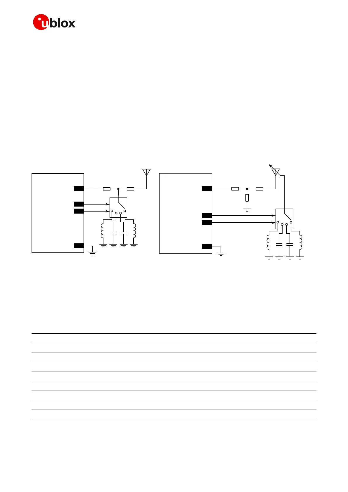
Figure 50 shows the example application circuits implementing impedance tuning and aperture
tuning. The module controls an RF switch which is responsible for selecting the appropriate matching
element for the operating band. Table 32 reports suggested components implementing the SP4T RF
switch functionality.
In Figure 50(a), tuning the antenna impedance optimizes the power delivered into the antenna by
dynamically adjusting the RF impedance seen by ANT pin of SARA-R5 series module. By creating a
tuned matching network for each operating band, the total radiated power (TRP) and the total
isotropic sensitivity (TIS) metrics are improved.
In Figure 50(b), antenna aperture tuning enables higher antenna efficiency over a wide frequency
range. The dynamically tunable components are added to the antenna structure itself, thereby
modifying the effective electrical length of the radiating element. Thus the resonant frequency of the
antenna is shifted into the module’s operating frequency band. Aperture tuning optimizes radiation
efficiency, insertion loss, isolation, and rejection levels of the antenna.
Figure 50: Examples of schematics for cellular antenna dynamic impedance tuning (a) and aperture tuning (b).
☞ Refer to the antenna datasheet and/or manufacturer for proper values of matching components
Z1, Z2, Z3, L1, L2, C1, C2. These components should have low losses to avoid degrading the
radiating efficiency of the antenna, thereby hindering the positive effects of dynamic tuning.

 Loading...


