SARA-R5 series - System integration manual
UBX-19041356 - R04 System description Page 8 of 118
C1-Public
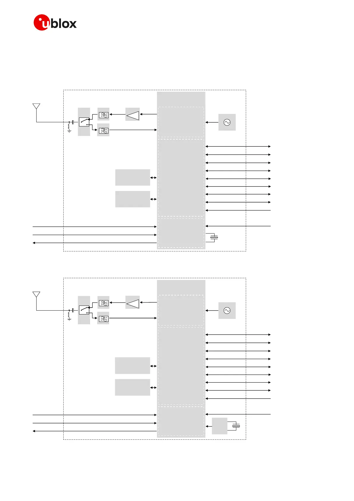
1.2 Architecture
Figure 1, Figure 2 and Figure 3 summarize the internal architecture of the SARA-R500S modules,
SARA-R510S modules, and SARA-R510M8S modules, respectively.

 Loading...


